Display device

Inactive Publication Date: 2006-11-23
138 EAST LCD ADVANCEMENTS LTD +1
View PDF47 Cites 42 Cited by
  • Summary
  • Abstract
  • Description
  • Claims
  • Application Information

AI Technical Summary

Benefits of technology

[0012] The display device of the invention can provide a LCD display with enhanced contrast in both the bright and dark environments.

Problems solved by technology

However, in an environment where external light is strong such as out of doors in the daytime, contrast can not be obtained enough.
Since this reflective LCD uses external light as a light source, there is a problem that the display can not be made in an environment of no external light.
However, since this semi-transmissive LCD has a transmissive region and a reflective region in a pixel, there is a problem of low display efficiency in each of the pixels.
Therefore, the small amount of light leaks from the transparent acrylic plate 110 to reach the eyes of the viewer 113, causing a problem of degrading the contrast of a LCD display.

Method used


Image

  • Display device
  • Display device
  • Display device

Examples


first embodiment

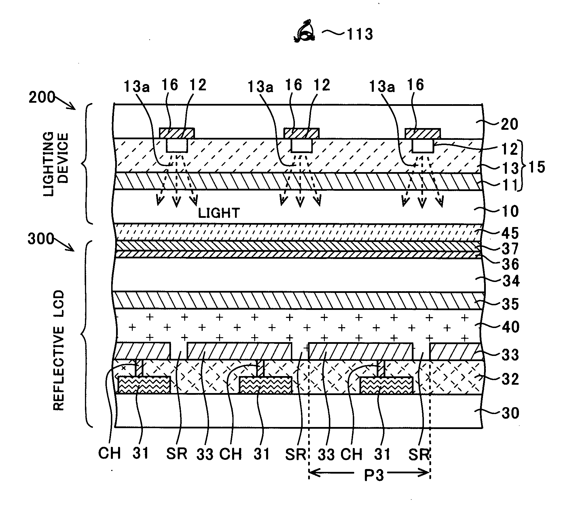
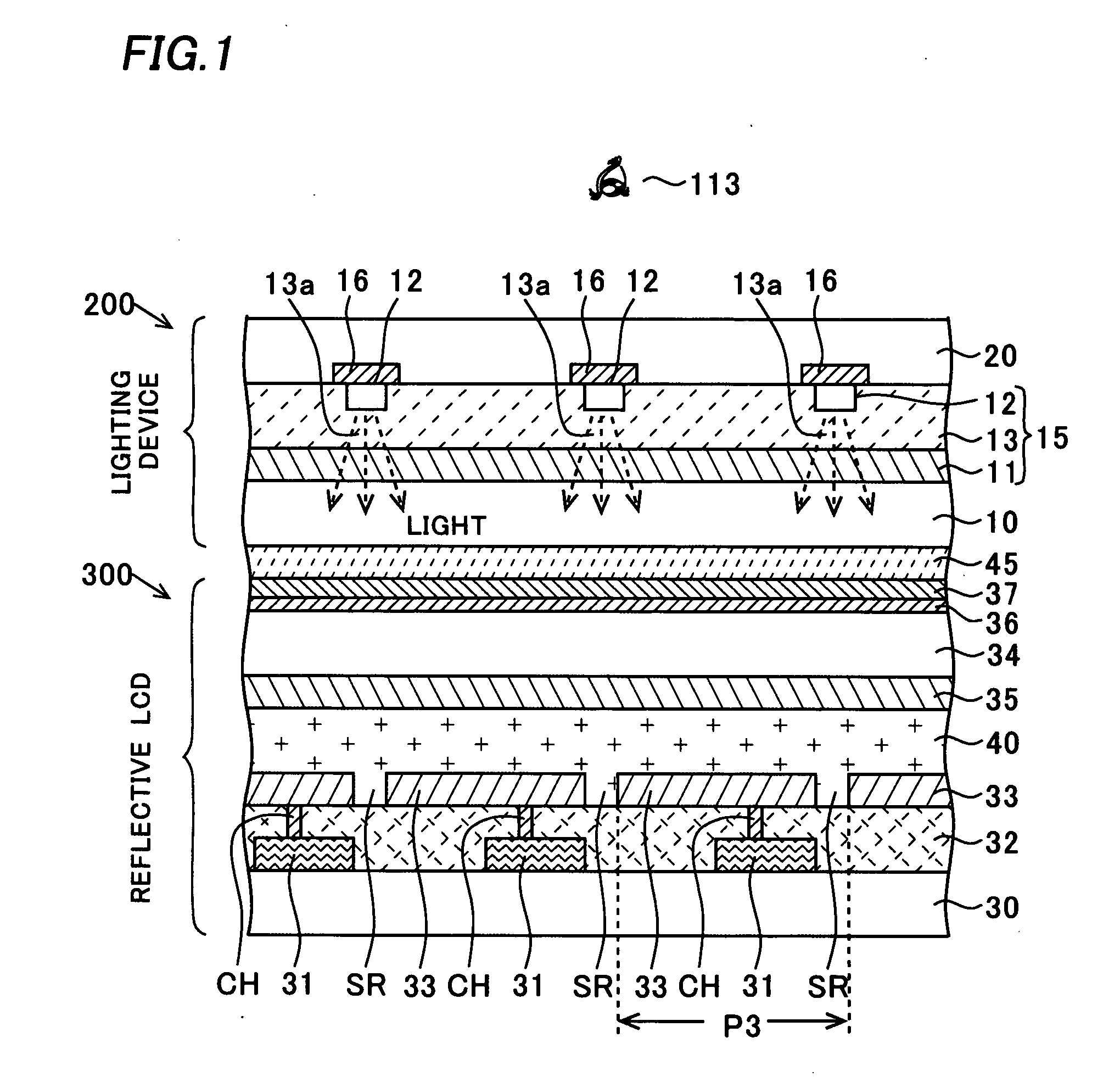
[0027] A display device of the invention will be described referring to figures. FIG. 2 is a plan view of a reflective LCD 300 provided with a lighting portion 200 of this embodiment on the lighting portion 200 side, and FIG. 1 is a cross-sectional view of FIG. 2 along line X-X. In this embodiment, the lighting portion 200 is disposed above the reflective LCD 300, being opposed to a display surface of the LCD 300 as shown in FIG. 1.

[0028] The structure of the lighting portion 200 will be described first. An organic electroluminescent element layer 15 (hereafter, abbreviated to an “organic EL element layer 15”) is interposed between a transparent substrate 10 and a transparent substrate 20 made of a glass substrate or the like. The organic EL element layer 15 includes an anode layer 11 made of a transparent conductive material such as ITO (Indium Tin Oxide) or IZO (Indium Zinc Oxide) and formed on substantially the whole surface of the transparent substrate 10, an organic layer 13 fo...

fourth embodiment

[0079] Next, a display device of the invention will be described referring to figures.

[0080] This embodiment describes a modification of the structure of the lighting portion 200 of the first and third embodiments. There is no modification to the structure of the reflective LCDs 300 and 300A.

[0081]FIG. 12 is a cross-sectional view of a lighting portion 200A. FIG. 13 is a schematic perspective view of the lighting portion 200A. FIGS. 12 and 13 show one of a plurality of organic EL elements 25 in the organic EL element layer 15.

[0082] A step forming layer 26 is formed on a first transparent substrate 61 (corresponds to the transparent substrate 10 of the first embodiment) in a region for forming the organic EL element 25 as shown in FIG. 12. This step forming layer 26 is made of transparent resin such as photosensitive acrylic resin. An anode 27 made of a transparent conductive material such as ITO (Indium Tin Oxide) or IZO (Indium Zinc Oxide) is formed on the step forming layer 26....


PUM


Abstract

The invention is directed to the higher contrast in a liquid crystal display device (LCD) having a lighting portion as a front light. A lighting portion is formed by interposing an organic EL layer between a transparent substrate and a transparent substrate. A light shield layer is formed covering a cathode layer of the organic EL element layer. The lighting portion is disposed above the reflective LCD. The reflective LCD has a polarizing plate, a light scattering layer, an opposing substrate, a common electrode, a liquid crystal layer, and a TFT substrate. When the refractive indexes of seven layers of an anode layer, the transparent substrate, a resin layer, the polarizing plate, the light scattering layer, the opposing substrate, and the common electrode are defined as n(1), n(2), n(3), n(4), n(5), n(6), and n(7) respectively, the relation of 1.33>n(k) / n(k+1)>0.75(k=1-6) holds.

Description

CROSS-REFERENCE OF THE INVENTION [0001] This invention is based on Japanese Patent Applications Nos. 2005-148541, 2005-148545, 2005-199434 and 2005-213453, the contents of which are incorporated herein by reference in its entirety. BACKGROUND OF THE INVENTION [0002] 1. Field of the Invention [0003] The invention relates to a display device having a lighting portion. [0004] 2. Description of the Related Art [0005] A liquid crystal display device (hereafter, referred to as a LCD) is thin and consumes low power in its characteristics, and has been broadly used as a monitor of a computer or a monitor of a mobile data terminal such as a cellular phone. There are a transmissive LCD, a reflective LCD, and a semi-transmissive LCD as the LCD. In the transmissive LCD, a transparent electrode is used as a pixel electrode for applying a voltage to a liquid crystal and a back light is set in the rear of the LCD, so that a bright display can be realized by controlling a transmission amount of lig...

Claims


Application Information

Patent Timeline
IPC IPC(8): H01L29/04
CPCG02F1/133553G02F2001/133616G02F1/133603G02F1/133616G02F1/1335
Inventor KOMA, NORIO
Owner 138 EAST LCD ADVANCEMENTS LTD
Why Eureka
Try Eureka