
Machine tool

a technology of machine tools and tuning circuits, which is applied in the direction of manufacturing tools, instruments, force/torque/work measurement apparatus, etc., can solve the problems of having to replace the amplifying unit with a new one, and it is not easy for workers to adjust the tuning circuit in a work site, so as to reduce the cost of maintenance, facilitate the operation, and reduce the damage of displacement sensors

Inactive Publication Date: 2006-11-23
TOKYO SEIMITSU +1
View PDF8 Cites 16 Cited by
  • Summary
  • Abstract
  • Description
  • Claims
  • Application Information

AI Technical Summary

Benefits of technology

The present invention provides a machine tool with a displacement sensor and an amplifying unit that can be easily adjusted and replaced in a work site. The machine tool includes an impedance adjustment circuit that can change the internal impedance constant of the tuning circuit connected to the displacement sensor. The displacement sensor and the amplifying unit can be connected by a detachable connector, and the machine tool can also include an eddy current sensor and a variable induction circuit for different types of displacement sensors. The technical effects of the invention include reducing maintenance costs and improving the evaluation of the impedance characteristic of the amplifying unit with respect to each displacement sensor.

Problems solved by technology

However, it is conventionally very difficult for a worker to adjust the tuning circuit in a work site.
For the above reasons, in the case where the displacement sensor is damaged, not only the damaged displacement sensor but also the amplifying unit must be replaced with a new one, which is uneconomical.

Method used


Image

  • Machine tool
  • Machine tool
  • Machine tool

Examples


first embodiment

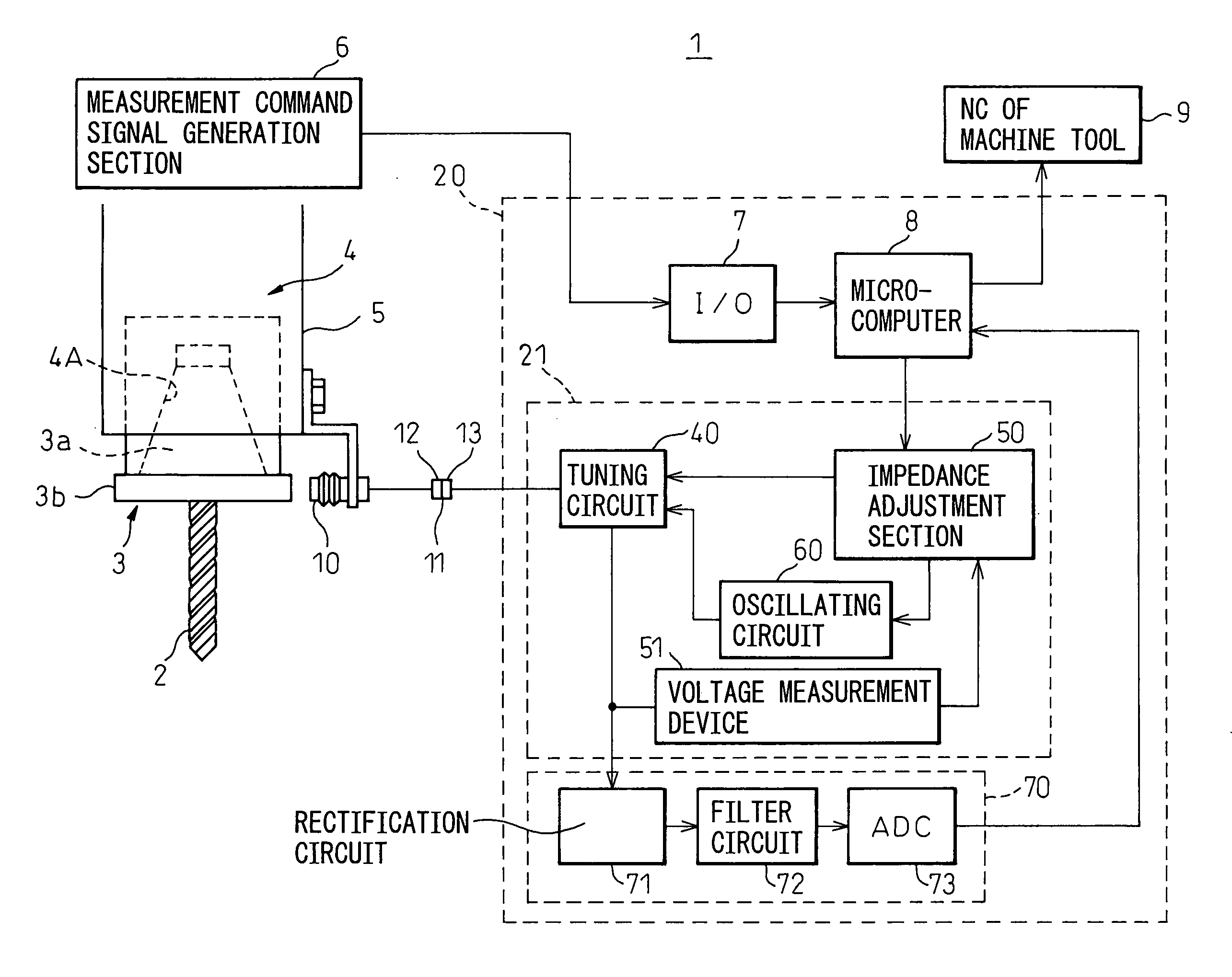
[0043]FIG. 3 is an arrangement view showing an outline of a machine tool of the present invention. A machine tool 1 is an MC in which various tools are automatically selected by an ATC device according to a machining process and the thus selected tool is automatically attached to a main spindle so as to conduct machining on a workpiece.

[0044] The present invention will be explained below by referring to the example of an MC. However, it should be noted that the present invention is not limited to the above specific embodiment. As long as it is a machine tool having a function of attaching and detaching a tool, the present invention can be widely applied. For example, the present invention can be applied to a machine tool such as a tapping machine or a compound lathe. A machine to which the present invention is applied is not necessarily provided with ATC function.

[0045] The machine tool 1 includes: a main spindle 4 to which a tool holder 3 having a tool 2 is attached; a displacemen...

second embodiment

[0108] The micro-computer 8 shown in FIG. 3 may be a low electric current consumption type micro-computer 8a used for control which controls a circuit such as an eddy current sensor 10 or a sensor drive circuit 21 in the second embodiment shown in FIG. 13 and a micro-computer 8b used for calculation which judges an abnormality of a state in which the tool holder 3 is attached to the main spindle according to the measurement data collected by the micro-computer 8a used for control.

[0109] The micro-computer 8b for calculation may be started only when a measurement command signal is generated by the measurement command signal generation section 6. In this way, electric power consumed by the micro-computer 8b and used for calculation can be saved.

[0110]FIG. 14 is a flow chart for explaining a function of automatically turning on and off an electric power source of the micro-computer 8b used for calculation in a machine tool shown in FIG. 3.

[0111] In the loop of steps S11 and S12, the ...


PUM


Abstract

A machine tool in which a tool holder having a tool is attached to a main spindle and the main spindle is rotated to conduct machining on a workpiece, comprises: a displacement sensor, the impedance of which is changed according to a distance from the displacement sensor to the tool holder, an AC signal being impressed upon the displacement sensor from an amplifying unit, wherein an abnormality of a state, in which the tool holder is attached to the main spindle, is judged from a signal level appearing in the displacement sensor. The machine tool further comprises: a tuning circuit connected to the displacement sensor, the tuning circuit composing a resonance circuit together with the displacement sensor; and an impedance adjustment circuit for adjusting an internal impedance constant of the tuning circuit.

Description

BACKGROUND OF THE INVENTION [0001] 1. Field of the Invention [0002] The present invention relates to a technique for adjusting a measurement device for measuring a distance to a tool holder in order to judge an abnormality of a state in which the tool holder is attached to a machine tool having a rotary shaft. More particularly, the present invention relates to a machine tool having a sensor which can be easily replaced when the above measurement device is automatically adjusted in a machine tool in which a tool holder such as a machining center, which will be referred to as an “MC” hereinafter, is used. [0003] 2. Description of the Related Art [0004] An MC is a device in which various tools are automatically selected according to a machining process and the thus selected tool is automatically attached to a main spindle so as to conduct various types of machining. In this MC, tools are replaced by an automatic tool changing device (ATC). Using this ATC device, a tool holder, to whic...

Claims


Application Information

Patent Timeline
Patent Type & Authority Applications(United States)
IPC IPC(8): G08B21/00
CPCB23Q17/003G01D18/008G01D5/2013
Inventor TAKAKU, MASAKAZU
Owner TOKYO SEIMITSU
Learn More