Multichannel time encoding and decoding of a signal

Inactive Publication Date: 2006-11-23
THE TRUSTEES OF COLUMBIA UNIV IN THE CITY OF NEW YORK
View PDF12 Cites 22 Cited by
  • Summary
  • Abstract
  • Description
  • Claims
  • Application Information

AI Technical Summary

Benefits of technology

[0010] It is an object of the present invention to reduce the average spike rate from the output of a time encoding

Problems solved by technology

While traditional A/D conversion techniques have been effective, techniques based on amplitude sampling have limitations.
While digital signals can be readily processed at the lower supply voltages, traditional synchronous sampling of the amplitude of a signal becomes more difficult as the available power supply voltage is reduced and each bit in the A/D or D/A converter reflects a substantially lower voltage increment.
A problem with this approach is that the ASDM introduces non-linearities in z(t) which cannot be recovered using a linear decimati

Method used


Image

  • Multichannel time encoding and decoding of a signal
  • Multichannel time encoding and decoding of a signal
  • Multichannel time encoding and decoding of a signal

Examples


Embodiment Construction

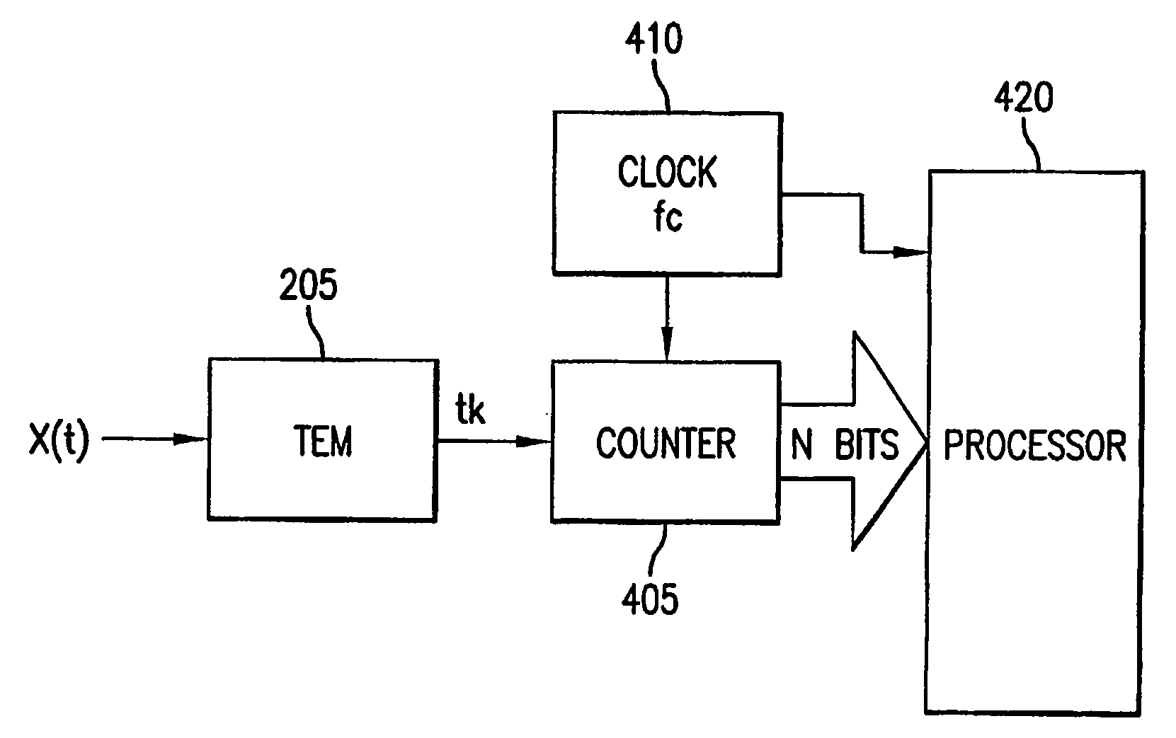
[0033] The present invention uses time encoding to digitize an analog signal and also uses appropriate non-linear decoding methods for subsequent recovery of the input signal. Thus, the systems and methods described apply to analog-to-digital (A / D) conversion and digital-to-analog (D / A) conversion using time encoding of a signal. In particular, the current invention employs a multichannel encoding and decoding approach which provides reduced average trigger times from each of the time encoding machines (TEM) used in the signal encoding process.

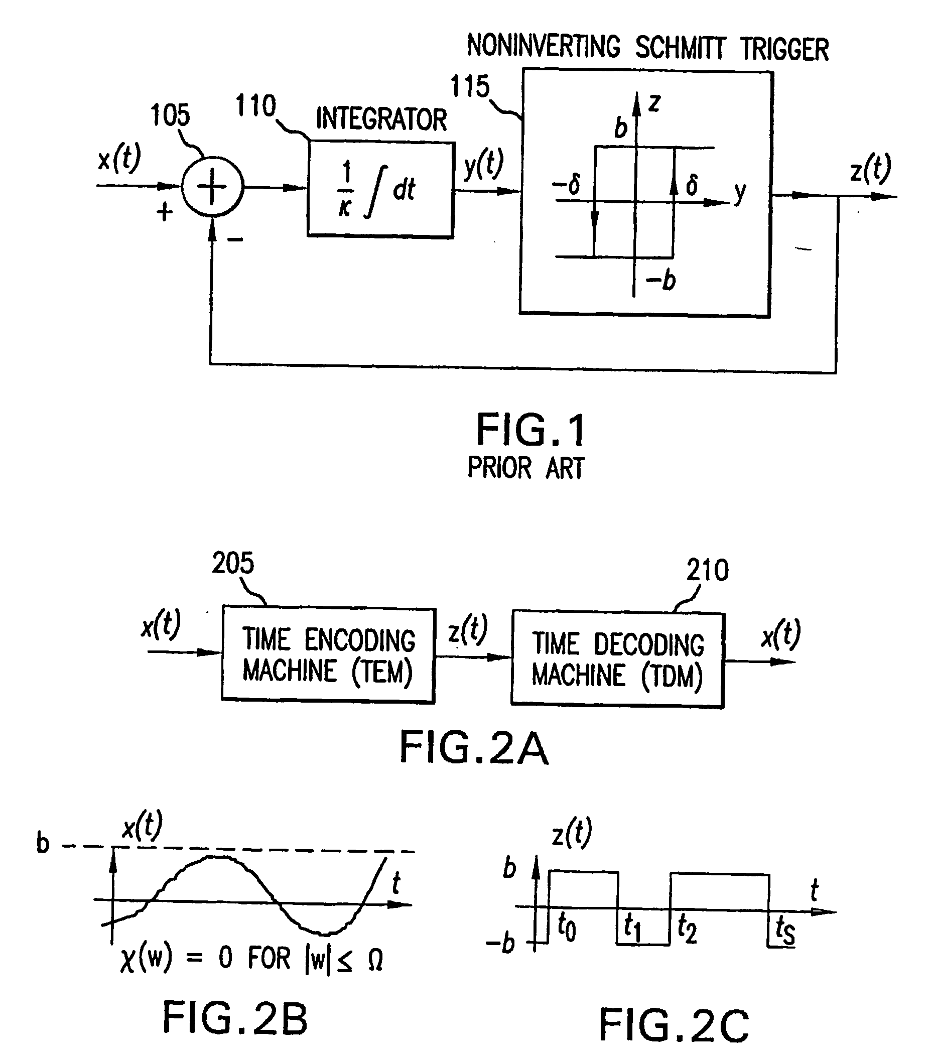
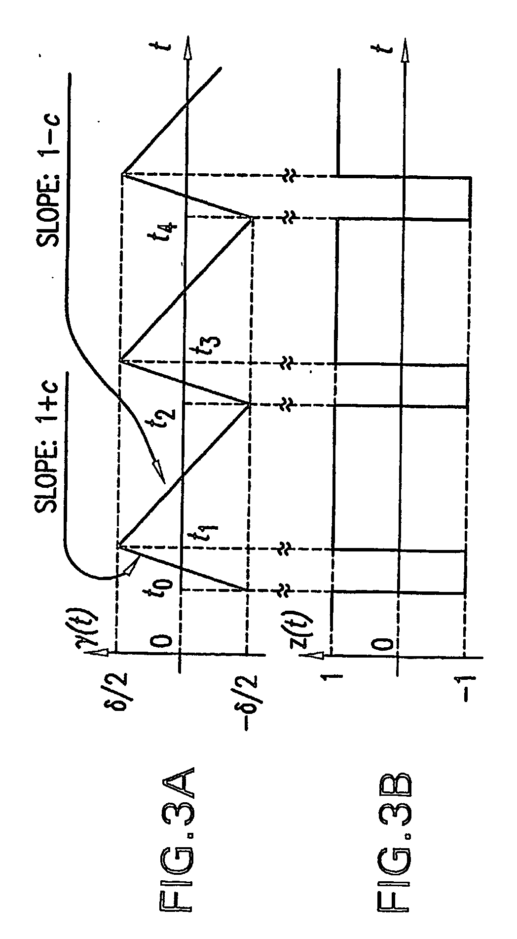
[0034] In the present application, the operation and implementation of time encoding machines (TEM) and time decoding machines (TDM) are provided. As used herein, a TEM is a circuit or process which receives a bounded input signal and generates an asynchronous set of binary transitions, the timing of which are related to the amplitude of the input signal. More generally, a TEM is a circuit or process which maps amplitude information into time...


PUM


Abstract

Analog signals can be fully encoded as an asynchronous time sequence generated by a time encoding machine. With knowledge of the parameters of the time encoding machine, the asynchronous time sequence can be decoded using a non-linear time decoding machine. Such a system can be extended into an encoder/decoder in which a signal is processed in M separate channels. An input signal is applied to the encoder where the signal is provided to an M channel encoder circuit including a filter bank having a total bandwidth partitioned among M adjacent or overlapping filters. Each of the M filters are coupled to a corresponding one of M time encoding machines. The encoder output is represented by M sets of time encoded trigger values. The input signal can be recovered from the M sets of time encoded trigger values by applying the trigger signals to a corresponding M channel decoder which includes M TDMs and filters. The TDMs recover the continuous signal from each channel. The filter outputs xm are then amplitude scaled sm and are combined to recover the input signal. By partitioning the signal bandwidth into M channels, the average pulse rate from each TDM is substantially reduced.

Description

CROSS-REFERENCE TO RELATED APPLICATION FIELD OF THE INVENTION [0001] The present invention relates generally to signal processing and more particularly relates to circuits and methods for recovering a signal from the output of a time encoding machine which maps amplitude information into an asynchronous time sequence. BACKGROUND OF THE INVENTION [0002] Most signals in the world in which we live are analog, i.e., cover a continuous range of amplitude values. However, most computer systems for processing these signals are binary digital systems. Generally, synchronous analog-to-digital (A / D) converters are used to capture analog signals and present a digital approximation of the input signal to a computer processor. That is, at precise moments in time synchronized to a system clock, the amplitude of the signal of interest is captured as a digital value. When sampling the amplitude of an analog signal, each bit in the digital representation of the signal represents an increment of volt...

Claims


Application Information

Patent Timeline
IPC IPC(8): H03M7/00H03M1/12H03M3/02H04L
CPCH03M1/125H03M1/121H03M1/50H03M3/504H03M1/82H03M3/468H03M3/432H03M1/662
Inventor LAZAR, AUREL A.
Owner THE TRUSTEES OF COLUMBIA UNIV IN THE CITY OF NEW YORK
Why Eureka
Try Eureka