
Computer simulation of body dynamics including a solver that solves for position-based constraints

a computer simulation and solver technology, applied in the field of computer simulation of body dynamics, can solve the problems of computational cost and memory cost, and the approach above suffers from a number of problems, so as to reduce differences in positions and reduce differences

Inactive Publication Date: 2006-11-23
ELECTRONICS ARTS INC
View PDF4 Cites 18 Cited by
  • Summary
  • Abstract
  • Description
  • Claims
  • Application Information

AI Technical Summary

Benefits of technology

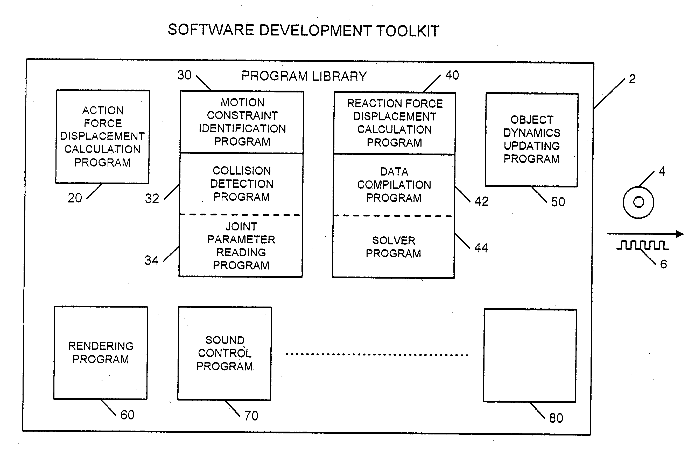
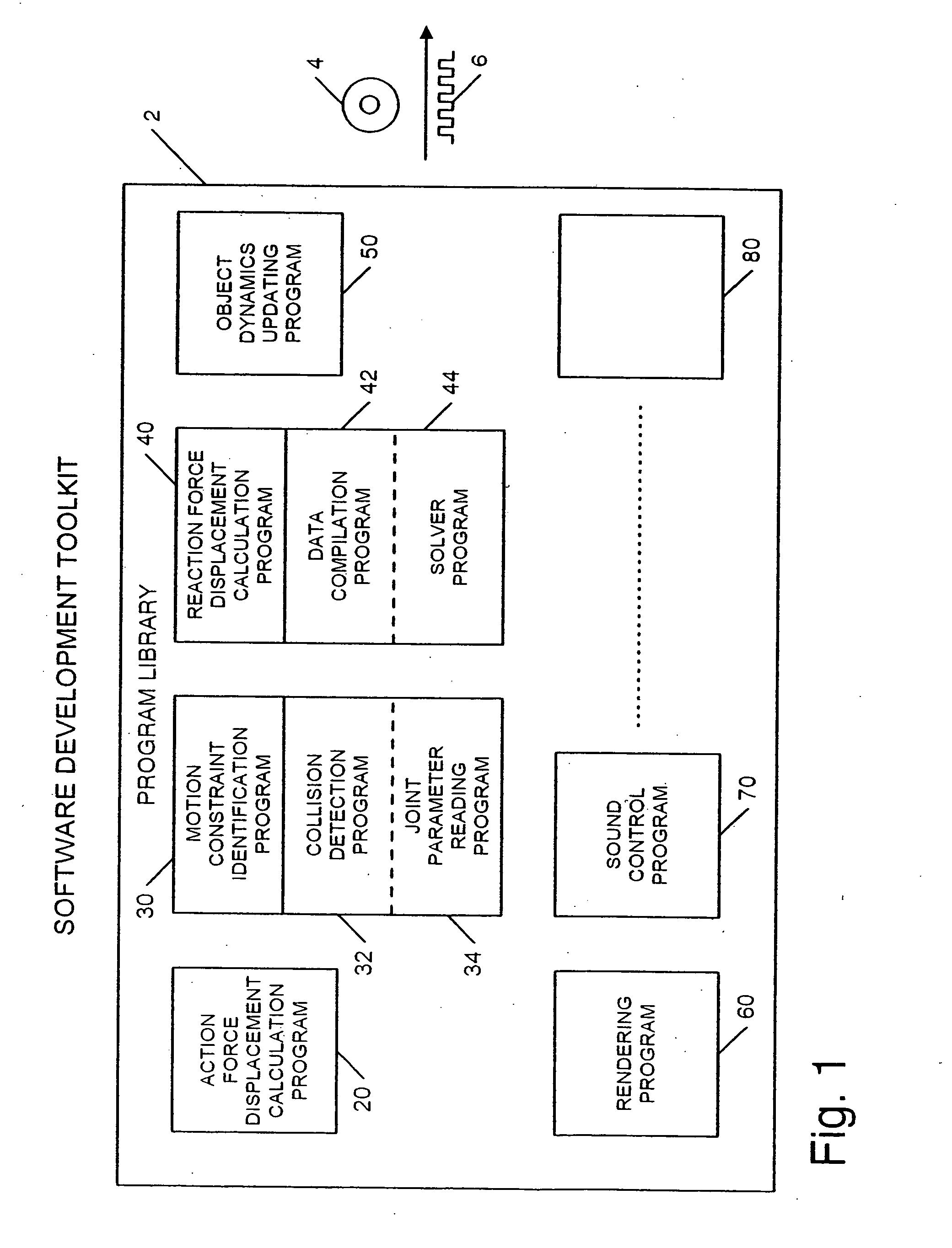
[0032] In embodiments of simulators according to the present invention that simulate motion of a plurality of rigid bodies, constraints on the plurality of rigid bodies are expressed in terms of positions or displacements of the bodies and positions or displacements that satisfy the constraints are calculated for the bodies at predetermined time steps. The predetermined time steps can be determined by the needs of a display system used to display simulated movement of simulated rigid bodies. Boundary conditions can be defined for each constraint acting on computer objects as a function of positions or displacements of the objects in order to generate equations to be solved to determine positions of the objects as influenced by the constraint. Positions of a plurality of objects under the influence of a constraint can be calculated by reducing differences in the positions of the objects in at least one direction and solving an equation including the positions with reduced differences.

Problems solved by technology

For example, if a video game character was an articulated body with arms and legs and a scene involved that character moving, it would not be realistic if the character's forearm temporarily separated from the character's upper arm at the elbow during a body movement.
A particular problem is to prevent bodies from simultaneously occupying the same space at the same time (known as object penetration) by calculating non-penetration constraint forces to keep the objects apart.
The approach above suffers from a number of problems, however.
Calculating the transpose of J is therefore both computationally expensive and memory expensive, even though the calculation itself is straightforward.
Further, the memory storage and computation time requirements increase in proportion to the square of the number of constraints represented by J. Evaluation of the transpose of J is therefore particularly problematic for computer game consoles which typically do not provide extensive processing capability or extensive memory.
Not only is this restrictive, but it is also time-consuming.
Thirdly, errors in the calculated positions of the bodies often occur.
However, this constraint is only valid at the instant in time when the bodies touch—not before when the bodies are apart and not after when the bodies are penetrating.
However, not only does this add another step to the computation (increasing the number of processing operations and the processing time), but the movement of the bodies to their corrected positions imparts a velocity to the bodies which results in subsequent errors in the dynamics of the bodies.

Method used


Image

  • Computer simulation of body dynamics including a solver that solves for position-based constraints
  • Computer simulation of body dynamics including a solver that solves for position-based constraints
  • Computer simulation of body dynamics including a solver that solves for position-based constraints

Examples


Embodiment Construction

[0047] In embodiments of a simulator according to the present invention, constraint-based simulation of the interaction of rigid bodies is done where constraints are defined in terms of the displacements of the positions of the rigid bodies and displacements caused by constraint reaction forces when the bodies interact are calculated to ensure that the bodies comply with the displacement constraints.

[0048] The simulator can be devised of hardware specifically suited to the tasks or software executable by a general purpose programmable device (or other programmable device, such as a microprocessing system). While steps, operations and / or functions of the simulator are often described herein with reference to mathematical calculations, it should be understood that these calculations are performed by an electronic device or system. For example, it need not be explicitly stated, but it should be apparent that apparatus described herein could be used to perform matrix operations describ...


PUM


Abstract

Computer simulation of the dynamics of rigid bodies interacting through collisions, stacks and joints is performed using a constraint-based system in which constraints are defined in terms of the positions of the bodies.

Description

CROSS-REFERENCES TO RELATED APPLICATIONS [0001] This application claims priority from co-pending U.S. Provisional Patent Application No. 60 / 664,642 filed Mar. 23, 2005 entitled “POSITION-BASED SOLVER” which is hereby incorporated by reference, as if set forth in full in this document, for all purposes. [0002] The present application is filed of even date with the following commonly assigned applications / patents: [0003] U.S. patent application Ser. No. ______ filed Mar. 23, 2006 entitled “COMPUTER SIMULATION OF BODY DYNAMICS INCLUDING A SOLVER THAT SOLVES IN LINEAR TIME FOR A SET OF CONSTRAINTS” [Attorney Docket No. 019491-010710US], in the name of Jean-Christophe Leprevost (hereinafter “Leprevost II); [0004] U.S. patent application Ser. No. ______ filed Mar. 23, 2006 entitled “COMPUTER SIMULATION OF BODY DYNAMICS INCLUDING A SOLVER THAT SOLVES IN LINEAR TIME FOR A SET OF CONSTRAINTS USING VECTOR PROCESSING” [Attorney Docket No. 019491-010810US], in the name of Jean-Christophe Leprev...

Claims


Application Information

Patent Timeline
Patent Type & Authority Applications(United States)
IPC IPC(8): G06G7/48G06F9/44G06T15/00G06T13/20
CPCA63F13/10A63F2300/64G06T2210/21G06T13/20A63F2300/643A63F13/56
Inventor LEPREVOST, JEAN-CHRISTOPHE
Owner ELECTRONICS ARTS INC
Learn More