Co-deployed optical referencing for responsive dust-based sensing system

a dust-based sensing system and co-deployment technology, applied in the field of apparatus and methods for calibrating optical detectors, can solve the problems of difficult detection of pollution cloud, difficulty in detecting pollution cloud, and material invisible and otherwise undetectable by human beings, and achieve high optical reflectivity, high optical absorption, and high gain reference signal

Active Publication Date: 2006-11-23
THE BOEING CO
View PDF13 Cites 4 Cited by
  • Summary
  • Abstract
  • Description
  • Claims
  • Application Information

AI Technical Summary

Benefits of technology

[0006] In a first preferred embodiment, the present invention provides a co-deploy optically oscillating mirror device as part of a warfare agent responsive dust (WARD) system. The convex reference mirror device (RMD) incorporates structures (e.g., fins or rotors) that induce rotation of the RMD as it falls with the WARD. The RMD mass density and aerodynamic drag are designed to produce similar rates-of-fall for the RMDs and the WARD particles. The RMDs incorporate alternating regions of high optical reflectivity and high optical absorption, over the entire spectral range of interest for the FORWARD measurement. For cases when the collection optics employ an adjacent laser for the illuminating source, retroreflectors give a very high gain reference signal. Alternative embodiments provide optical references that employ actively controlled reflectance. In the current embodiment, devices are provided that are designed to optically oscillate between a low and a high reflectivity value employing electro-optic materials in an optically or electronically controlled structure. These active devices may be powered by the optical illumination source, or by batteries on the reference.

Problems solved by technology

Clouds of pollution and other airborne materials are difficult to detect.
The difficulty of detecting these clouds arise for several reasons.
First, the materials may be invisible and otherwise undetectable by human beings even at concentration levels that pose an immediate health threat.
Second, the clouds tend to move with the wind so that, once released, they can travel long distances, thereby appearing without warning.
Also, because these clouds might be found at some height above the ground, it may not be possible to place an instrument in the cloud short of flying a probe into the cloud.
Thus, where a particular cloud might be found is subject to a number of vagaries that cause difficulties in predicting where the cloud might exist.
However, this practice suffers from several problems also.
Maintaining the alignment can be quite difficult because, at times, either the source, sensor cloud, or detector will move relative to one and other.
Also, environmental factors along the path that the light travels from the source, to the sensors, and then to the detector may cause an attenuation of the light at some of the frequencies that the sensor attenuates reflected light.
As a result, when the light arrives at the detector from the sensor, it is difficult to ascertain whether the attenuation of the light was caused by the sensor's exposure to the material or due to the environmental factors.

Method used


Image

  • Co-deployed optical referencing for responsive dust-based sensing system
  • Co-deployed optical referencing for responsive dust-based sensing system
  • Co-deployed optical referencing for responsive dust-based sensing system

Examples


Embodiment Construction

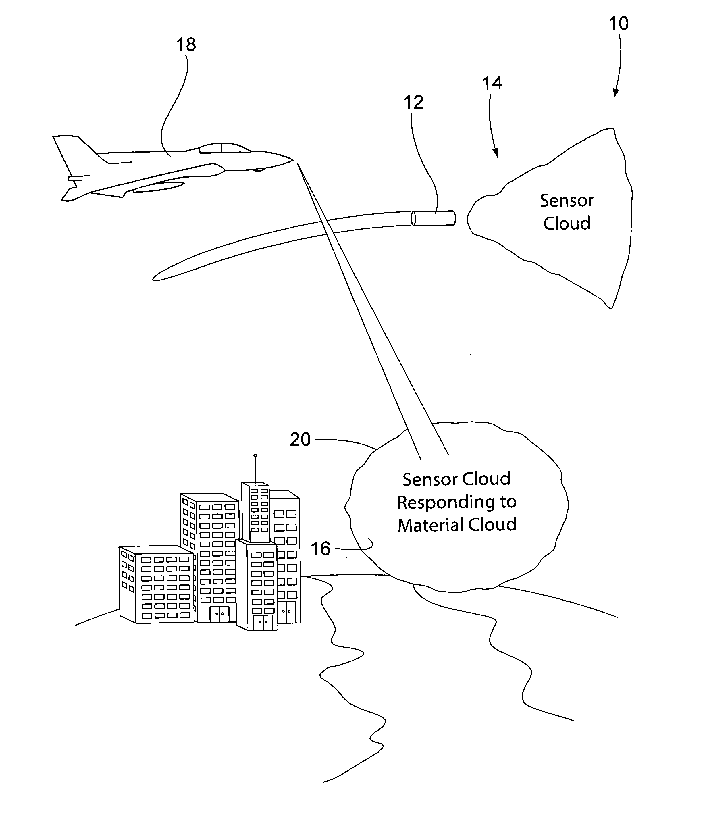
[0020] Referring to the accompanying drawings in which like reference numbers-indicate like elements, FIG. 1 illustrates a system 10 constructed in accordance with the principles of the present invention.

[0021] The system 10 of FIG. 1 includes a deployment mechanism, two clouds 14 and 16 of optical sensors, and a vehicle 18 that includes an optical detector. Also, FIG. 1 shows a cloud 20 of airborne material that can be, for example, a pollutant, a chemical or biological agent, or other impurity in the air. The cloud 16 of sensors is shown, at least partly, as being coincident with the cloud of material 20 whereas the cloud 14 of sensors is shown being spaced apart from the cloud 20. Where the sensors of the cloud 16 are in contact with the material cloud 20 the material reacts with the porous silicon of the sensors and causes the sensors to reflect a different spectrum than the spectrum reflected by the sensors in the unaffected sensor cloud 14.

[0022] In operation, deployment mec...


PUM


Abstract

Apparatus and methods for calibrating an optical detector. In a preferred embodiment, the present invention provides a reference that includes a body and a surface of the body. At least a portion of the surface has a reflectance that can vary. The reference is adapted to be deployed with a cloud of optical sensors and has a terminal velocity that is about the same as the terminal velocity of the sensors. Further, the variation of the reflectance can be caused by a rotation of the reference (caused by an aerodynamic member) or by a controller that controls an electo optic material of the surface. In a preferred embodiment, the sensors are porous silicon optical sensors and the reference includes a retroreflector. The invention also provides a method of referencing an optical signal. The method includes deploying a reference with a cloud of sensors and detecting a variation in its reflectance.

Description

[0001] This application is related to and incorporates by reference U.S. patent application Ser. No. ______, entitled Enhanced Signal Detection of Optically Encoded Particles via Flare, and filed by Koshinz on ______.FIELD OF THE INVENTION [0002] This invention relates generally to apparatus and methods for calibrating optical detectors, and, more particularly, apparatus and methods for calibrating remote optic detectors used in conjunction with a cloud of porous silicon optical sensors to detect airborne chemicals. BACKGROUND OF THE INVENTION [0003] Clouds of pollution and other airborne materials are difficult to detect. Yet the concentration of these materials needs to be measured to enable those near the cloud to respond in an appropriate manner. Without an accurate assessment of the strength of the cloud unnecessary evacuations may be ordered or a needed evacuation may not be deemed necessary. The materials that can occur in these clouds include man-made pollution (e.g. a relea...

Claims


Application Information

Patent Timeline
Patent Type & Authority Applications(United States)
IPC IPC(8): G01J1/10
CPCG01J3/42G01N21/783G01S7/495G01N2021/7773G01N2021/1793
Inventor HAGER, HAROLD E.SHERMAN, WILLIAM D.
Owner THE BOEING CO
Why Eureka
Try Eureka