Fuel cell system

a fuel cell and system technology, applied in the field of fuel cell systems, can solve the problems of increasing the cost of the combustor (catalyst), reducing the size of such a hydrogen off-gas discharge mechanism, and reducing the output of a unit cell of the fuel cell, so as to reduce the quantity of catalyst used, the effect of stable catalyst

Inactive Publication Date: 2006-11-23
TOYOTA JIDOSHA KK
View PDF9 Cites 32 Cited by
  • Summary
  • Abstract
  • Description
  • Claims
  • Application Information

AI Technical Summary

Benefits of technology

[0040] According to the aforementioned first to third aspects of the invention, since it is possible to suppress the pulsed change (fluctuation) in the flow quantity of the hydrogen off-gas or the concentration of hydrogen in the hydrogen off-gas that is discharged from the fuel cell intermittently (or continuously) such that the flow quantity or the concentration of hydrogen is made uniform, it is possible to make the effect of the catalyst stable and to reduce the used quantity of the catalyst. Thus, it is possible to perform the combustion treatment for the hydrogen off-gas using a small combustor.

Problems solved by technology

Also, humidifying water in the hydrogen gas and water generated due to electrochemical reaction remain in the fuel cell, which inhibits electrochemical reaction, and decreases output of a unit cell of the fuel cell.
Particularly, in the case of an in-vehicle fuel cell system, since a space where the fuel cell system is mounted is limited, size of such a hydrogen off-gas discharge mechanism needs to be reduced.
Also, since platinum which is generally expensive is used in the catalyst in the combustor, the cost of the combustor (catalyst) is high if the size of the combustor (catalyst) is large.

Method used


Image

  • Fuel cell system
  • Fuel cell system
  • Fuel cell system

Examples


first embodiment

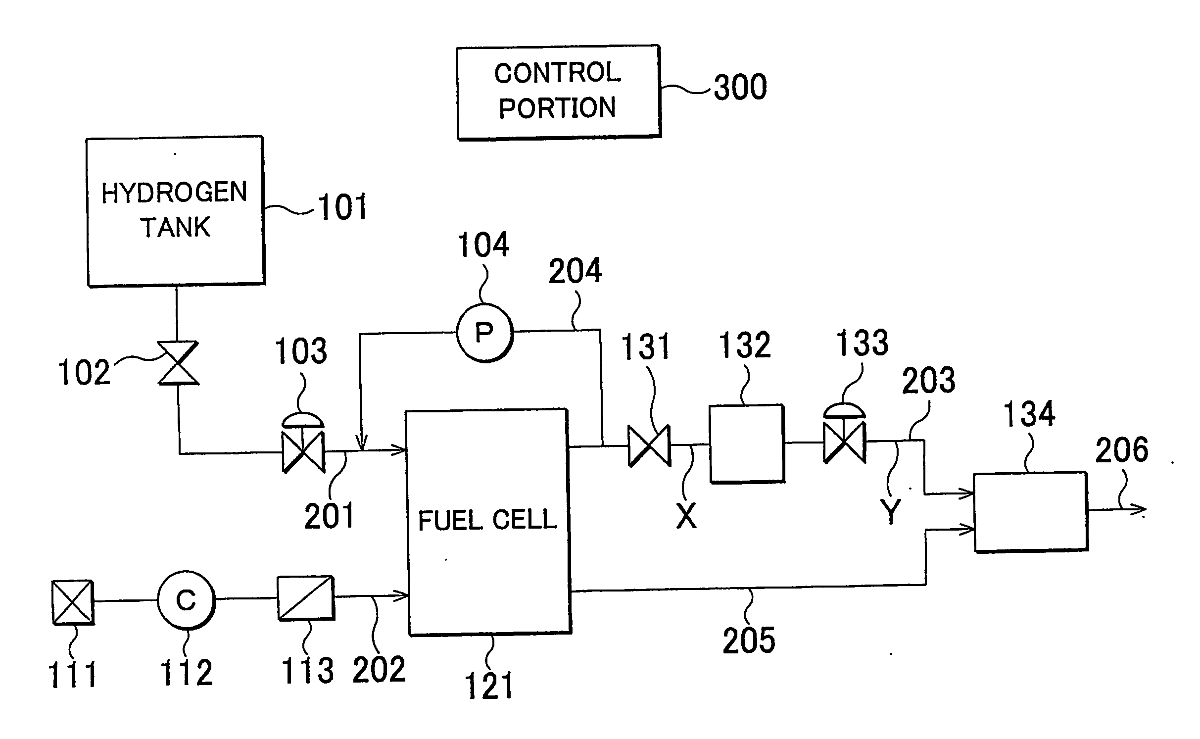
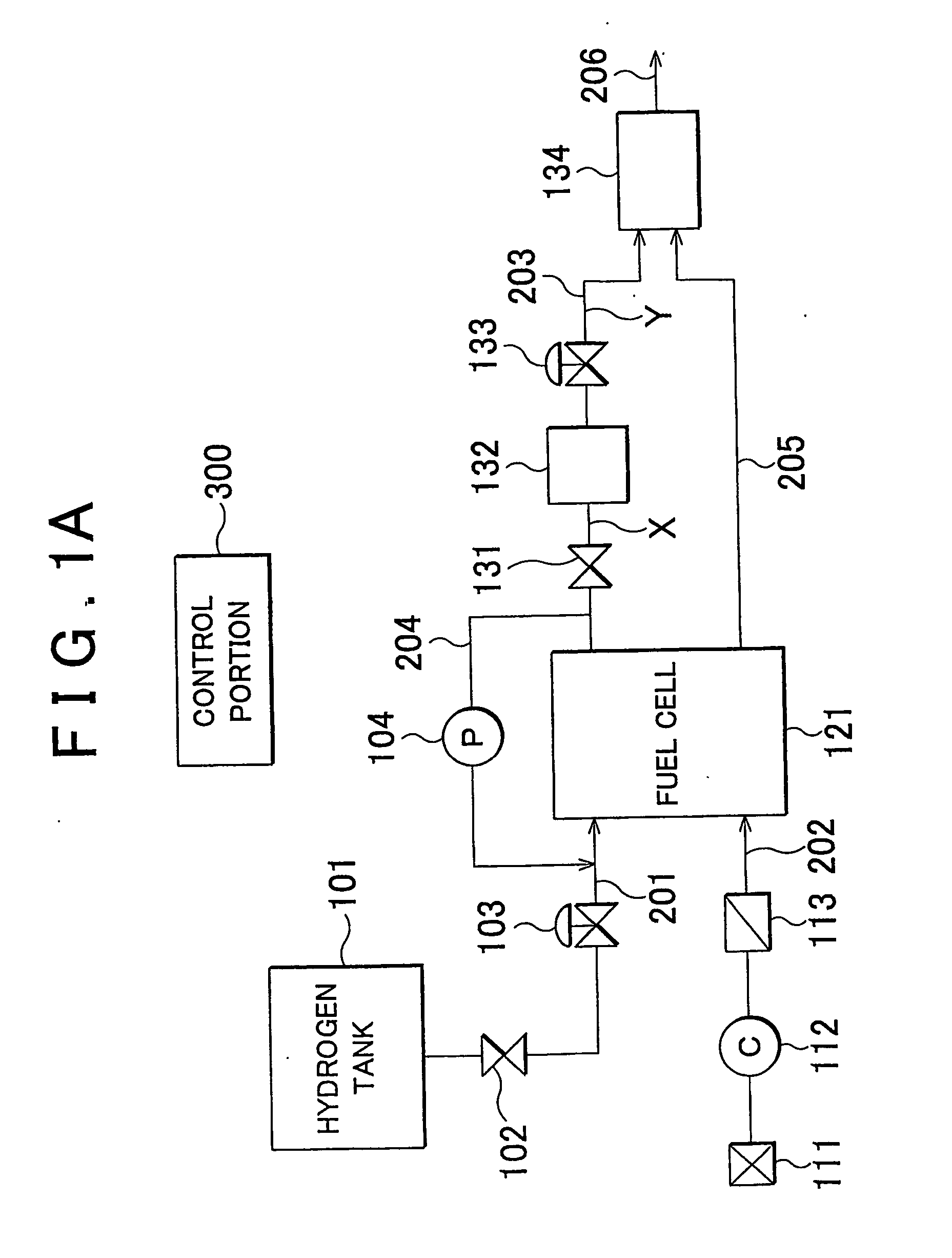
[0061]FIG. 1A to FIG. 1C schematically show a first embodiment of the invention. FIG. 1A shows a high-pressure hydrogen tank 101 for storing hydrogen, an opening / closing valve (shutoff valve) 102 for interrupting supply of hydrogen gas from the high-pressure hydrogen tank 101, a pressure adjusting valve 103 for adjusting the pressure (flow quantity) of the hydrogen gas supplied to a fuel cell 121, and a pump 104 for causing exhaust gas (hydrogen off-gas) containing remaining hydrogen gas that has not been used to flow back to the fuel cell 121. FIG. 1A also shows an air filter 111 for removing dust in the air, a compressor 112 for delivering air, and a humidifier 113 for humidifying air. The fuel cell 121 is, for example, a polymer electrolyte fuel cell. The fuel cell receives supply of hydrogen gas and air (oxidizing gas) to generate electric power. FIG. 1A also shows an opening / closing valve 131 for discharging the hydrogen off-gas to the outside of the fuel cell 121, a chamber 13...

third embodiment

[0074]FIG. 3 shows a third embodiment of the invention. In FIG. 3, the same portions as in FIG. 1 are denoted by the same reference numerals, and description thereof will be omitted.

[0075] In the embodiment, as the flow quantity control valve (adjusting valve) 133, an electromagnetic valve is used, and is controlled by output of the control portion 300. The other portions are the same as in the first embodiment.

[0076] In the configuration, the control portion 300 sets the opening amount of the adjusting valve 103 according to the accelerator opening amount of the vehicle so as to set the quantity of the hydrogen gas supplied to the fuel cell 121. Also, the control portion 300 sets the average value of the quantity of the hydrogen off-gas supplied to the combustor 134 from the flow quantity adjusting valve 133 according to the accelerator opening amount of the vehicle. Thus, it is possible to set the quantity of the hydrogen off-gas supplied to the combustor 134 according to the qu...

fourth embodiment

[0079]FIG. 4 shows a fourth embodiment of the invention. In FIG. 4, the same portions as in FIG. 1 are denoted by the same reference numerals, and description thereof will be omitted.

[0080] In the embodiment, a temperature sensor 136 for measuring the temperature of the catalyst in the combustor 134 is provided. Output of the temperature sensor 136 is transmitted to the control portion 300. The flow quantity control valve (adjusting valve) 133 for suppressing the pulsed change in the quantity of the hydrogen off-gas and supplying the hydrogen-off gas to the combustor 134 is constituted by an electromagnetic valve. Also, a sufficient quantity of the air off-gas is supplied to the combustor 134. The other portions are the same as in the first embodiment.

[0081] In the configuration, the control portion 300 adjusts the quantity of the hydrogen off-gas supplied from the flow quantity control valve 133 based on the output of the temperature sensor 136 such that the temperature of the ca...


PUM

PropertyMeasurementUnit
concentrationaaaaaaaaaa
temperatureaaaaaaaaaa
pressureaaaaaaaaaa

Abstract

A fuel cell system which reduces a quantity of hydrogen in hydrogen off-gas discharged from a fuel cell, and then discharges the hydrogen off-gas to atmosphere, includes an adjusting valve that suppresses a pulsed change in a flow quantity of hydrogen off-gas, which is intermittently discharged from the fuel cell to an exhaust passage and therefore flows in the exhaust passage in a pulse manner, such that the flow quantity becomes constant (stable).

Description

[0001] This is a 371 national phase application of PCT / IB2004 / 002694 filed 18 Aug. 2004, claiming priority to Japanese Patent Application No. JP 2003-317287 filed 9 Sep. 2003, and No. JP 2004-107828 filed 31 Mar. 2004, the contents of which are incorporated herein by reference.BACKGROUND OF THE INVENTION [0002] 1. Field of the Invention [0003] The invention relates to a fuel cell system and an electric vehicle using the fuel cell system. More particularly, the invention relates to improvement of a fuel cell system in which remaining hydrogen is caused to flow back. [0004] 2. Description of the Related Art [0005] A fuel cell receives supply of hydrogen gas and oxygen gas (oxidizing gas) to generate electric power. Gas containing remaining hydrogen that has not been consumed in the fuel cell is discharged to the outside of the fuel cell as hydrogen off-gas. Also, gas containing remaining oxygen that has not been consumed in the fuel cell is discharged to the outside of the fuel cell a...

Claims


Application Information

Patent Timeline
Patent Type & Authority Applications(United States)
IPC IPC(8): H01M8/04H01M8/06
CPCH01M8/04231H01M8/0662Y02T90/32Y02E60/50H01M2250/20Y02T90/40
Inventor YANAGI, TAKUOYAMAGISHI, NORIOFUJITA, NOBUO
Owner TOYOTA JIDOSHA KK
Why Eureka
Try Eureka