Motor, motor device, and lens drive mechanism using the same

a technology of lens drive mechanism and motor, which is applied in the direction of generator/motor, machine/engine, instruments, etc., can solve the problems of generating a small torque, reducing the diameter of the crank mechanism, and difficult pivotal rotation of the rotor

Inactive Publication Date: 2006-11-30
KONICA MINOLTA INC
View PDF6 Cites 43 Cited by
  • Summary
  • Abstract
  • Description
  • Claims
  • Application Information

AI Technical Summary

Benefits of technology

[0010] According to an aspect of the invention, a motor comprises: a base block; a rotary member which is rotatably supported on the base block, and includes a contact portion on an outer periphery thereof for outputting a rotating force; an oscillatory ring which includes a contact portion on an inner periphery thereof, and is oscillated on a plane perpendicular ...

Problems solved by technology

In the above conventional crank mechanism, a displacement amount of each SMA actuator is significantly small, and a sufficient pivotal rotation of the rotor is difficult by the mechanism having the small number of SMA actuators as proposed in the conventional arrangement.
Also, if the number of the SMA actuators is decreased, the crank diameter of the crank mechanism is decreased, which means generation of a small torque.
The increased number of the SMA actuators leads to generation of a large torque, however, it may lower the rotation number of the rotor, make the assembling of the crank mechanism complicated, and raise the production cost.
However, a required response time...

Method used


Image

  • Motor, motor device, and lens drive mechanism using the same
  • Motor, motor device, and lens drive mechanism using the same
  • Motor, motor device, and lens drive mechanism using the same

Examples


first embodiment

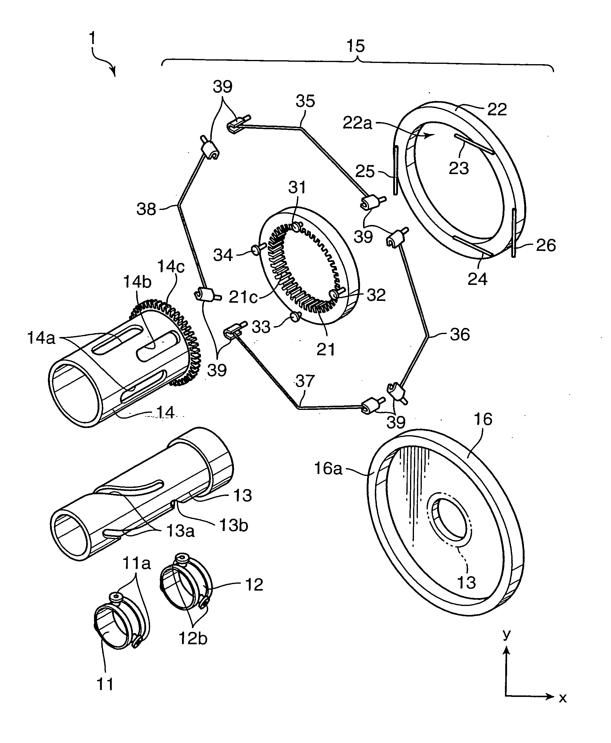
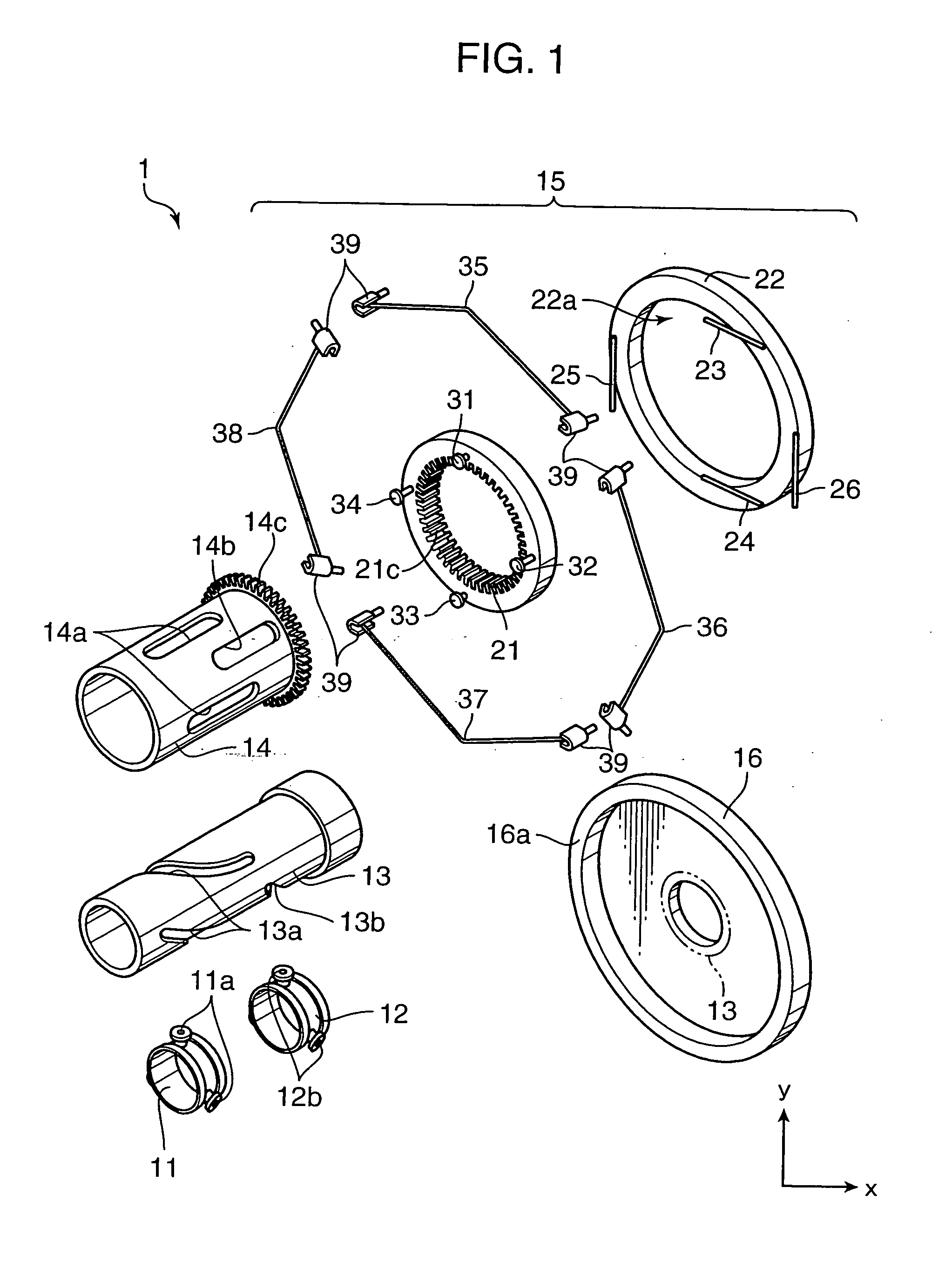
[0028]FIG. 1 is a perspective view showing a construction of a zoom unit for use in an image sensing apparatus, which serves as a lens drive mechanism in accordance with a first embodiment of the invention. The zoom unit 1 includes ring frames 11, 12 for supporting an unillustrated lens element on respective inner surfaces thereof, a fixed cylinder 13, a cylindrical cam 14, and a driver assembly 15. The zoom unit 1 is mounted on a base block 16.

[0029] The ring frames 11 and 12 has three projections 11a and 12b, respectively. The ring frames 11 and 12 are accommodated in the fixed cylinder 13 and the cylindrical cam 14 in this order in such a manner that the projections 11a of the ring frame 11 are received in a through groove 13a of the fixed cylinder 13 and in corresponding through grooves 14a of the cylindrical cam 14, and the projections 12b of the ring frame 12 are received in a through groove 13b of the fixed cylinder 13 and in corresponding through grooves 14b of the cylindri...

second embodiment

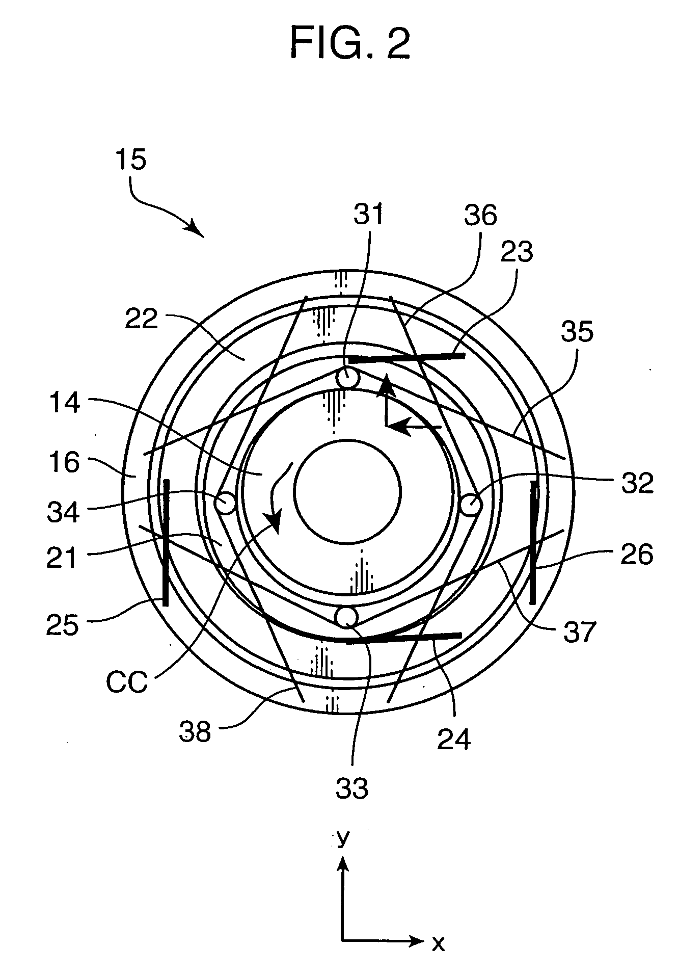
[0043]FIG. 4 is an illustration schematically showing a construction of a driver assembly 15′ in a zoom unit for use in an image sensing apparatus, which serves as a lens drive mechanism in accordance with a second embodiment of the invention. FIG. 5 is a cross-sectional view taken along the line X-X in FIG. 4. Elements in FIG. 4 which are equivalent to those in FIG. 2 and have the same arrangement as the arrangement in FIG. 2 are denoted by the same reference numerals, and elements in FIG. 4 whose arrangement is similar to those in FIG. 2 are denoted by the like reference numerals with an apostrophe ′ attached thereto. In the driver assembly 15′, a drive gear 21 is directly supported on a base block 16′ by a support rod 41, in place of the intermediate frame 22 and the parallel spring pairs 23, 24; and 25, 26.

[0044] In this embodiment, at least one e.g. four support rods 41 are provided. In the case where the plural support rods 41 are provided, the support rods 41 are substantial...

third embodiment

[0046]FIG. 6 is an exploded perspective view showing an example of an arrangement of a focus lens drive mechanism (hereinafter, called as “focus unit”) in accordance with a third embodiment of the invention. The focus unit 2 includes a bias spring 51, a rectilinear guide cylinder 52, a focus lens element 53, a cylindrical cam 54, an annular gear 55, a position retaining guide 56, and a base block 57. In this arrangement, the focus lens element 53 is guided merely in an optical axis direction of the focus unit 2 by the rectilinear guide cylinder 52. Also, the focus lens element 53 comes into pressing contact with the cylindrical cam 54 by an urging force of the bias spring 51 acting in a forward direction along the optical axis of the focus unit 2. The cylindrical cam 54 has a cam surface 541 extending in the optical axis direction, and an outer cycloid gear 542 at a radially outer position. The cylindrical cam 54 is rotatably supported about the optical axis.

[0047] The ring-like an...


PUM


Abstract

An arrangement of the invention includes a base block 16, a cylindrical cam 14, as a rotary member, which is rotatably supported on the base block 16, and includes a contact portion on an outer periphery thereof for outputting a rotating force, a drive gear 21, as an oscillatory ring, which includes a contact portion on an inner periphery thereof, and is oscillated on a plane perpendicular to a rotation axis of the cylindrical cam 14 in contact with the contact portion of the cylindrical cam 14, parallel springs 23 through 26, as a position retainer, for retaining the position of the drive gear 21, and three or more shape metal alloy actuators (SMA) wires 35 through 38, as expandable and contractible actuators, with both ends of the each SMA wire being fixed to the base block 16 for contact with the drive gear 21.

Description

[0001] This application is based on Japanese Patent Application No. 2005-155498 and No. 2006-25885 filed on May 27, 2005, and Feb. 2, 2006, respectively, the contents of which are hereby incorporated by reference. BACKGROUND OF THE INVENTION [0002] 1. Field of the Invention [0003] The present invention relates to a motor for generating a rotation driving force using a shape memory alloy, a motor device, and a lens drive mechanism incorporated with the motor for use in an image sensing apparatus. [0004] 2. Description of the Related Art [0005] The shape memory alloy (SMA) is generally used for an actuator which is actuated in response to a change of ambient temperature. For instance, the SMA is used for a valve portion to regulate the temperature of hot water in a hot water system, or for the purpose of varying a ventilating opening in accordance with a temperature change of external air. In the above usage, it is often the case that the SMA is molded into a coil spring, which is use...

Claims


Application Information

Patent Timeline
IPC IPC(8): F01B29/10F02G1/04
CPCG02B7/102
Inventor KOSAKA, AKIRATANII, JUNICHISHIMIZU, YOSHIEWADA, SHIGERU
Owner KONICA MINOLTA INC
Why Eureka
Try Eureka