
Steerable drilling system and method

a drilling system and a technology of bottom holes, applied in the direction of directional drilling, survey, borehole/well accessories, etc., can solve the problems of sacrificing directional control, altering the drilling trajectory, and difficult sliding of the bha, so as to improve rigidity, reduce the effect of torque pdm and efficient us

Inactive Publication Date: 2006-11-30
HALLIBURTON ENERGY SERVICES INC
View PDF49 Cites 32 Cited by
  • Summary
  • Abstract
  • Description
  • Claims
  • Application Information

AI Technical Summary

Benefits of technology

[0039] It is an advantage of the present invention that the spacing between the bend in a PDM or RSD and the bit face may be reduced by providing a rotating shaft having a pin connection at its lowermost end for mating engagement with a box connection of a long gauge bit. This connection may be made within the long gauge of the bit to increase rigidity.
[0040] Another advantage of the invention is that a relatively low torque PDM may be efficiently used in the BHA when drilling a deviated borehole. Relatively low torque requirements for the motor allow the motor to be reliably used in high temperature applications. The low torque output requirement of the PDM may also allow the power section of the motor to be shortened.
[0041] A significant advantage of this invention is that a deviated borehole is drilled while subjecting the bit to a relatively consistent and low actual WOB compared to prior art drilling systems. Lower actual WOB contributes to a short spacing between the bend and the bit face, a low torque PDM and better borehole quality.
[0042] It is also an advantage of the present invention that the bottom hole assembly is relatively compact. Sensors provided substantially along the total gauge length may transmit signals to a measurement-while-drilling (MWD) system, which then transmits borehole information to the surface while drilling the deviated borehole, thus further improving the drilling efficiency.
[0043] A significant advantage of this invention is that the BHA results in surprisingly low axial, radial and torsional vibrations to the benefit of all BHA components, thereby increasing the reliability and longevity of the BHA.
[0044] Still another advantage of the invention is that the BHA may be used to drill a deviated borehole while suspended in the well from coiled tubing.

Problems solved by technology

While stabilizers are thus accepted components of steerable BHAs, the use of such stabilizers causes problems when in the steering mode, i.e., when only the bit is rotated and the motor slides in the hole while the drill string and motor housing are not rotated to drill a curved borehole section.
Motor stabilizers provide discrete contact points with the wellbore, thereby making sliding of the BHA difficult while simultaneously maintaining the desired WOB.
Directional control may be sacrificed, however, because the unstabilized motor can more easily shift radially when drilling, thereby altering the drilling trajectory.
A short bit gauge length is desired since, when in the steering mode, the side cutting ability of the bit required to initiate a deviation is adversely affected by the bit gauge length.
A long gauge on a bit is commonly used in straight hole drilling to avoid or minimize any build, and accordingly is considered contrary to the objective of a steerable system.
The accepted view has thus been that the use of a long gauge bit or a piggyback stabilizer immediately above a conventional short gauge bit, in a steerable BHA results in the loss of the drilling operator's ability to quickly change direction, i.e., they do not allow the BHA to steer or steering is very limited and unpredictable.
Most formations drilled by PDMs cannot be economically drilled by turbodrills, and the use of turbodrills to drill curved boreholes is very limited.
Turbodrills require a significant pressure drop across the motor to rotate the bit, which inherently limits the applications in which turbodrills can practically be used.
Power sections of conventional turbodrills are often 30 feet or more in length, and increasing the length of the turbodrill power section is both costly and adversely affects the ability of the turbodrill to be used in steerable applications.
Steering while sliding with a PDM is typically accompanied by significant drag, which may limit the ability to transfer weight to the bit.
Unlike positive differential mud motors, this system has no traditional, elastomer motor power section, a component subject to wear and environmental dependencies.
By removing the need for a power section with the rotary steerable system, torque is coupled directly through the drillpipe from the surface to the bit, thereby resulting in potentially longer bit runs.

Method used


Image

  • Steerable drilling system and method
  • Steerable drilling system and method
  • Steerable drilling system and method

Examples


Embodiment Construction

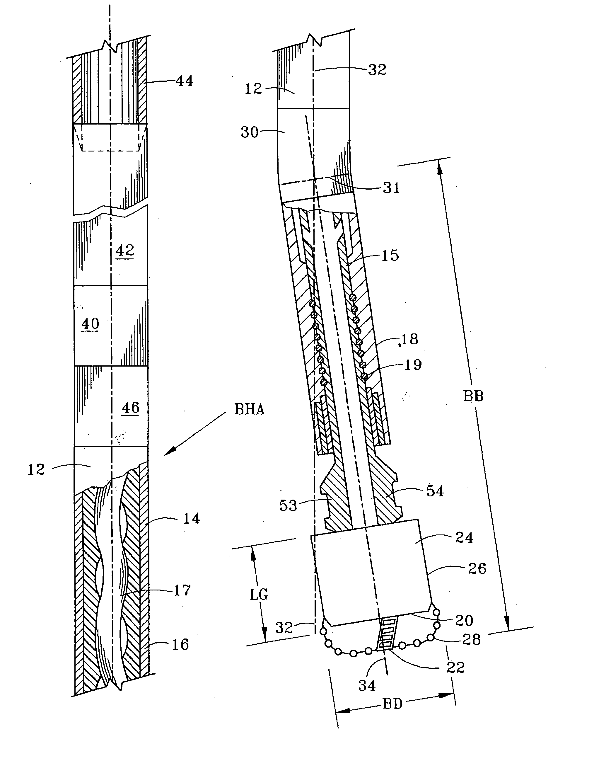
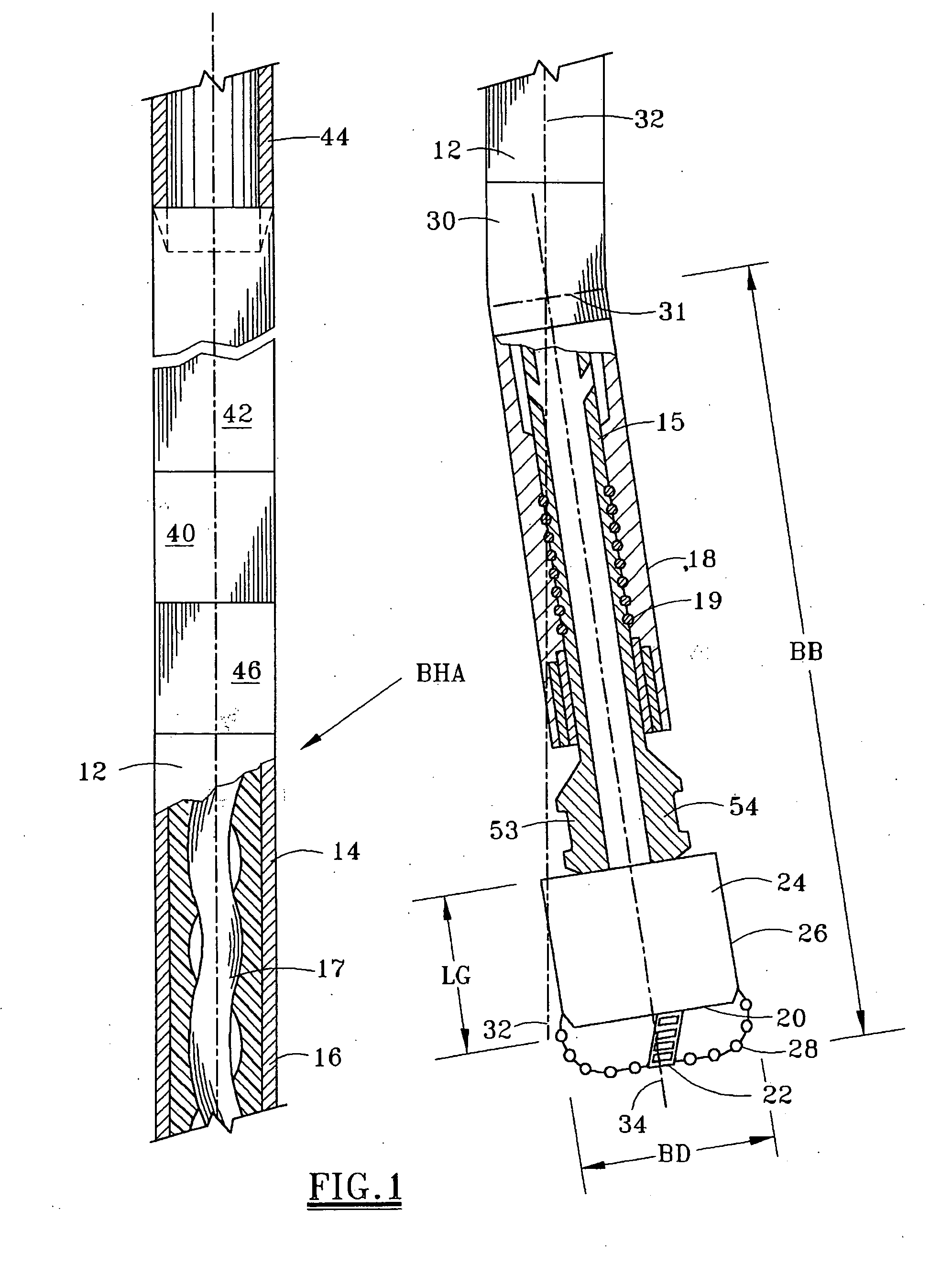
[0062]FIG. 1 depicts a bottom hole assembly (BHA) for drilling a deviated borehole. The BHA consists of a PDM 12 which is conventionally suspended in the well from the threaded tubular string, such as a drill string 44, although alternatively the PDM of the present invention may be suspended in the well from coiled tubing, as explained subsequently. PDM 12 includes a motor housing 14 having a substantially cylindrical outer surface along at least substantially its entire length. The motor has an upper power section 16 which includes a conventional lobed rotor 17 for rotating the motor output shaft 15 in response to fluid being pumped through the power section 16. Fluid thus flows through the motor stator to rotate the axially curved or lobed rotor 17. A lower bearing housing 18 houses a bearing package assembly 19 which comprising both thrust bearings and radial bearings. Housing 18 is provided below bent housing 30, such that the power section central axis 32 is offset from the low...


PUM


Abstract

A bottom hole assembly 10 for drilling a deviated borehole includes a positive displacement motor (PDM) 12 or a rotary steerable device (RSD) 110 having a substantially uniform diameter motor housing outer surface without stabilizers extending radially therefrom. In a PDM application, the motor housing 14 may have a fixed bend therein between an upper power section 16 and a lower bearing section 18. The long gauge bit 20 powered by the motor 10 may have a bit face 22 with cutters 28 thereon and a gauge section 24 having a uniform diameter cylindrical surface 26. The gauge section 24 preferably has an axial length at least 75% of the bit diameter. The axial spacing between the bit face and the bend of the motor housing preferably is less than twelve times the bit diameter. According to the method of the present invention, the bit may be rotated at a speed of less than 350 rpm by the PDM and / or rotation of the RSD from the surface.

Description

RELATED CASE [0001] Application Ser. No. 09 / 217,764 was issued as U.S. Pat. No. 6,269,892 and Continuation-In-Part application Ser. No. 09 / 378,023.FIELD OF THE INVENTION [0002] This continuation relates to application Ser. No. 09 / 217,764 which issued as U.S. Pat. No. 6,269,892 and Continuation-In-Part application Ser. No. 09 / 378,023. The present invention relates to a steerable bottom hole assembly including a rotary bit powered by a positive displacement motor or a rotary steerable device. The bottom hole assembly of the present invention may be utilized to efficiently drill a deviated borehole at a high rate of penetration. BACKGROUND OF THE INVENTION [0003] Steerable drilling systems are increasingly used to controllably drill a deviated borehole from a straight section of a wellbore. In a simplified application, the wellbore is a straight vertical hole, and the drilling operator desires to drill a deviated borehole off the straight wellbore in order to thereafter drill substanti...

Claims


Application Information

Patent Timeline
Patent Type & Authority Applications(United States)
IPC IPC(8): E21B7/04E21B7/06E21B7/08
CPCE21B7/067E21B47/01E21B7/068E21B47/013
Inventor CHEN, CHEN-KANG D.GAYNOR, THOMAS M.GLEITMAN, DANIEL D.HARDIN, JOHN R. JR.WALKER, COLINRAO, M. VIKRAMBOULTON, ROGER
Owner HALLIBURTON ENERGY SERVICES INC
Learn More