Al technical title is built by PatSnap Al team. It summarizes the technical point description of the patent document.
a position sensor and track technology, applied in the field of track, can solve problems such as improper airbag deployment, interference with the proper functioning of the seat position sensor, and preventing detection or sensing
Active Publication Date: 2006-11-30
TOUCHSENSOR TECH
View PDF9 Cites 68 Cited by
Summary
Abstract
Description
Claims
Application Information
AI Technical Summary
This helps you quickly interpret patents by identifying the three key elements:
Problems solved by technology
Method used
Benefits of technology
Problems solved by technology
Debris, for example, toys, wads of aluminum foil, bits of food, coins and other foreign objects, often accumulates on the floor and under the seat, and may interfere with proper functioning of the seat's position sensor.
Such debris may prevent detection or sensing of a target rail or object.
If the seat track position sensor fails to function, an improper seat position indication may be processed by the air bag deployment controller, resulting in improper air bag deployment.
As a result, the air bag may be deployed with an insufficient or excessive amount of force, resulting in injur
Method used
Image
Click on the blue label to locate the original text in one second.
Reading with bidirectional positioning of images and text.
Examples
Embodiment Construction
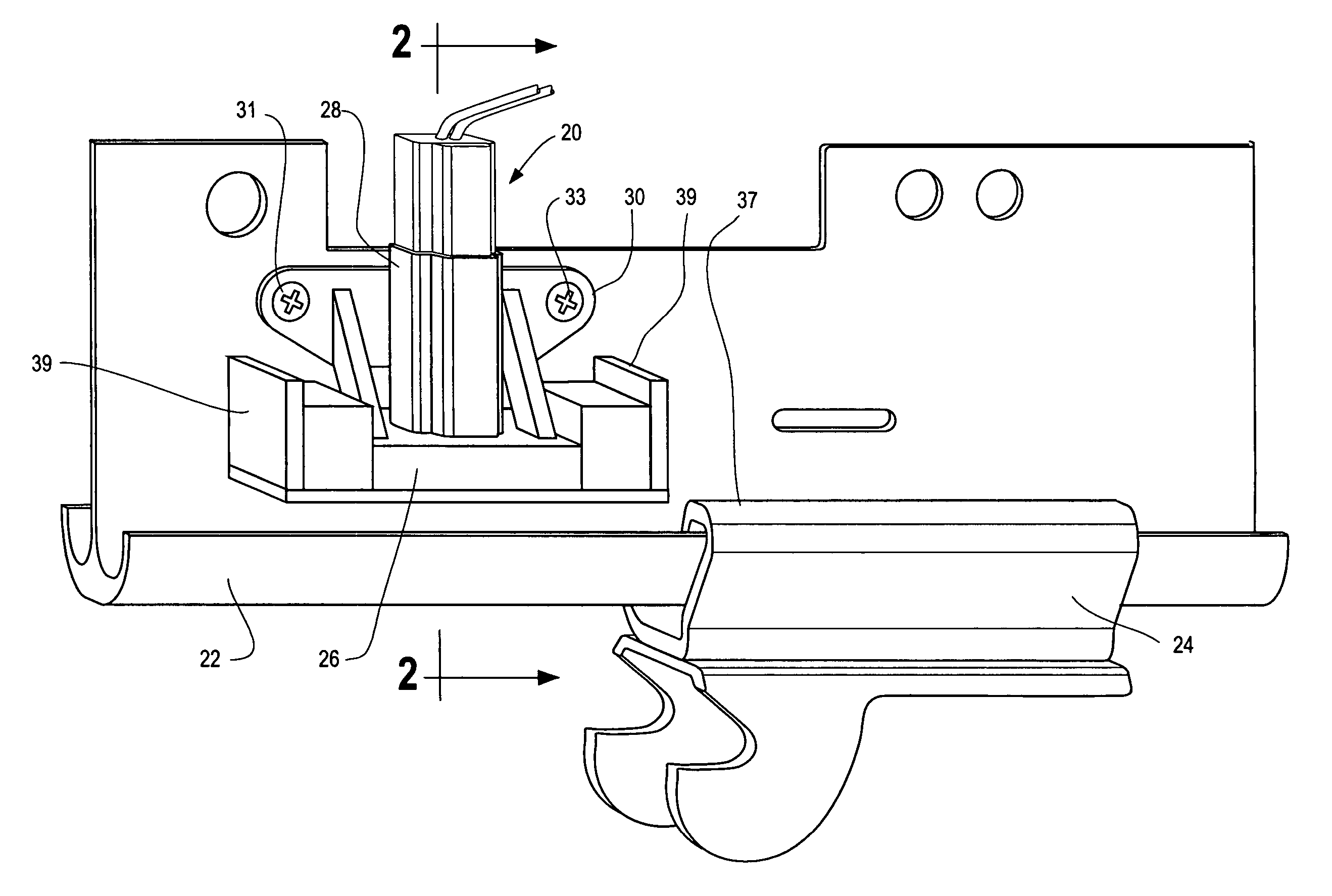
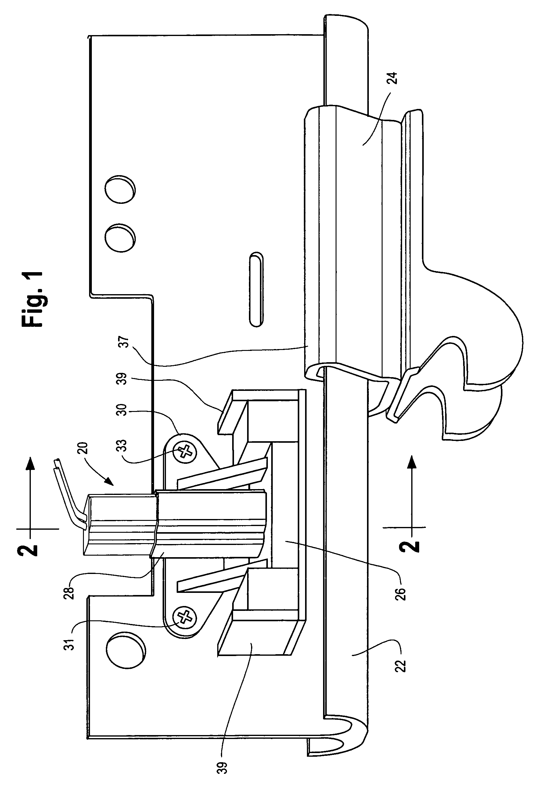
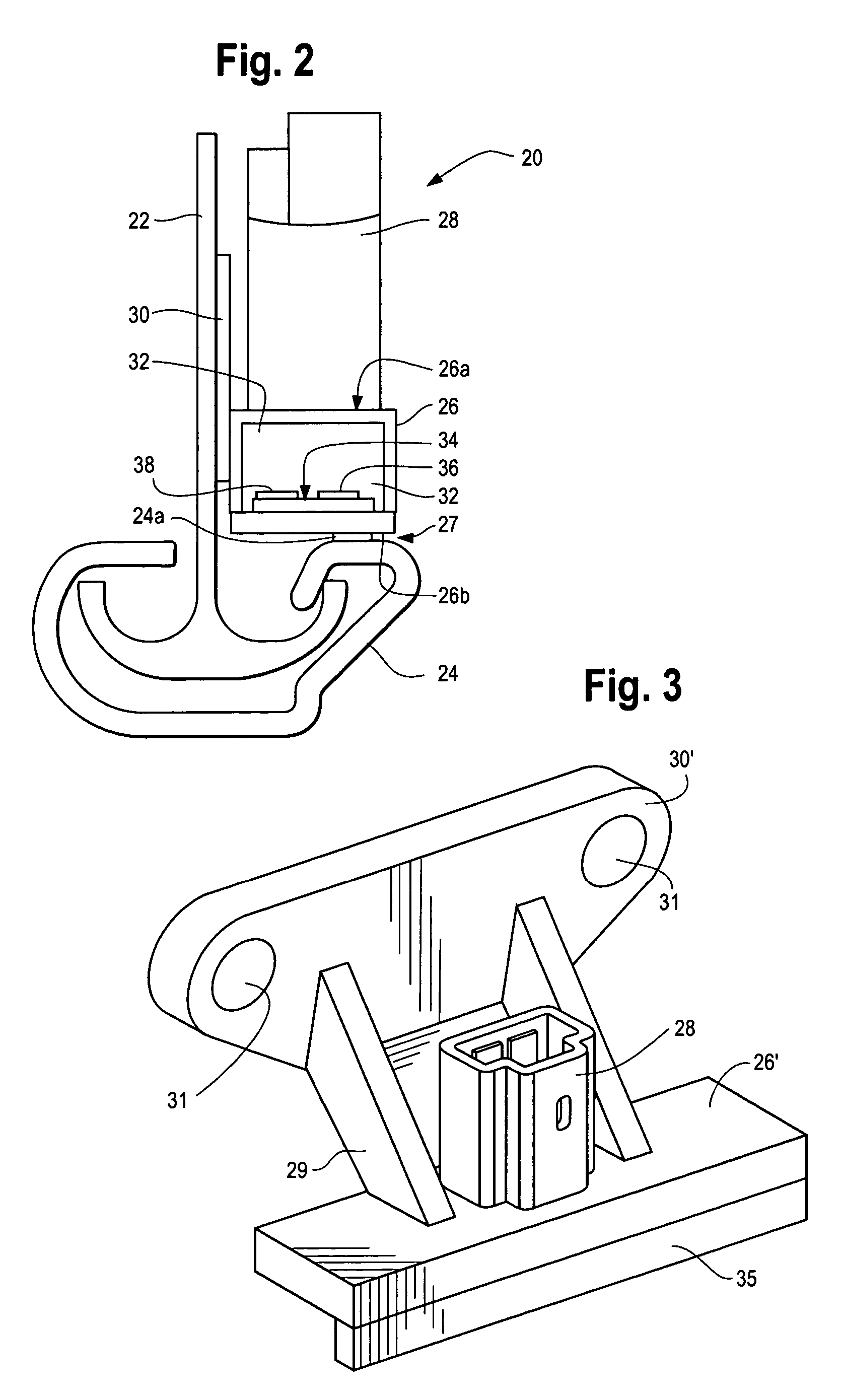
[0022] As best shown in FIGS. 1 and 2, a track position sensor 20 is secured to a first, movable rail 22 which is slidably received within a second, fixed rail 24. Sensor 20 includes a sealed protective housing 26 preferably made from a dielectric material such as polymer or fiber reinforced nylon. A sealable, releasable electrical connector 28 is disposed on an upper surface 26a of housing 26. Connector 28 provides first and second electrical connections to an interior cavity 32 of housing 26. Cavity 32 is sized to receive a sensor substrate 34, such as a printed circuit board (“PCB”), flexible circuit carrier, or the like. A clearance or air gap 27 is provided between a bottom surface 26b of housing 26 and second rail 24. Preferably, second rail 24 has a relatively wide, flat upper surface 24a.
[0023] Housing 26 may include first and second dielectric guard walls 39 that project upwardly from opposite ends of housing 26. Guard walls 39 sweep debris away from sensor assembly 20 whe...
PUM
Abstract
A low impedance sensor includes thin conductive electrodes on a dielectric substrate and detects proximity of a target metal object or structure moving along defined path such as a track. The sensor includes a first conductive electrode pad having a closed, continuous geometric form and a second conductive electrode surrounding the first electrode and spaced from the first electrode by a channel of non-conductive dielectric. The first and second electrodes are optionally disposed on the same surface of the substrate. An integrated control circuit is located on the substrate proximate the first and second electrodes, and is electrically coupled to the first and second electrodes.
Description
CROSS REFERENCE TO RELATED APPLICATIONS [0001] This application claims priority from and incorporates by reference the disclosure of U.S. Provisional Patent Application No. 60 / 638,197, filed Dec. 23, 2004. This application also claims priority from and incorporates by reference the disclosures of: U.S. Provisional Patent Application 60 / 638,200, filed on Dec. 23, 2004, and U.S. patent application Ser. No. ______, filed on Dec. 22, 2005, both entitled Shared Electrode Pattern Field Effect Sensor and Joystick; U.S. Provisional Patent Application 60 / 638,198, filed on Dec. 23, 2004, and U.S. patent application Ser. No. ______, filed on Dec. 22, 2005, both entitled Seat Control System; and U.S. Provisional Patent Application 60 / 638,159, filed on Dec. 23, 2004, and U.S. patent application Ser. No. ______, filed on Dec. 22, 2005, both entitled Keyless Entry Touch Pad System and Method.FIELD OF THE INVENTION [0002] The present invention relates to sensors or control actuators for detecting t...
Claims
Application Information
Patent Timeline
Application Date:The date an application was filed.
Publication Date:The date a patent or application was officially published.
First Publication Date:The earliest publication date of a patent with the same application number.
Issue Date:Publication date of the patent grant document.
PCT Entry Date:The Entry date of PCT National Phase.
Estimated Expiry Date:The statutory expiry date of a patent right according to the Patent Law, and it is the longest term of protection that the patent right can achieve without the termination of the patent right due to other reasons(Term extension factor has been taken into account ).
Invalid Date:Actual expiry date is based on effective date or publication date of legal transaction data of invalid patent.