Method for providing comprehensive electrical usage and demand data

Inactive Publication Date: 2006-11-30
HOWARD JOHN E
View PDF10 Cites 23 Cited by
  • Summary
  • Abstract
  • Description
  • Claims
  • Application Information

AI Technical Summary

Benefits of technology

[0036] The algorithms that are part of alternative embodiments of the method for providing comprehensive electrical usage and demand data are hig

Problems solved by technology

If the customer fails to observe these limits, the incentives may be lost, harsh penalties may be imposed, or both.
These services may or may not provide real-time data, depending upon the latency of the remote-reading data path.
Fixed wireless, satellite, and telephone access can theoretically approach real-time frequencies, but the communication service fees for thousands of accesses each month would become very costly, or even prohibitive.
Yet, the utility declared in testimony the California Public Utilities Commission in Application A.05-01, dated Jan. 20, 2005: “Due to technical and timing limitations, SCE cannot provide simultaneous real-time information to all approximately 13,000 large customers at this time.” It is impractical to access mobile wireless meters much more frequently than once per month.
But, network meters are not an immediate and universal solution for at least three reasons.
First, even though the number is growing, not all homes and businesses have the requisite network connection.
Second, adding real-time capability will dramatically increase the utility's burden in supporting its Internet-based information system.
Furthermore, this burden can be expected to peak during demand response events, when the need for real-time data is most acute, leaving the information system most vulnerable to failure.
Electric meters have relat

Method used


Image

  • Method for providing comprehensive electrical usage and demand data
  • Method for providing comprehensive electrical usage and demand data
  • Method for providing comprehensive electrical usage and demand data

Examples


Embodiment Construction

[0050] The description that follows is intended to be exemplary, and not limiting.

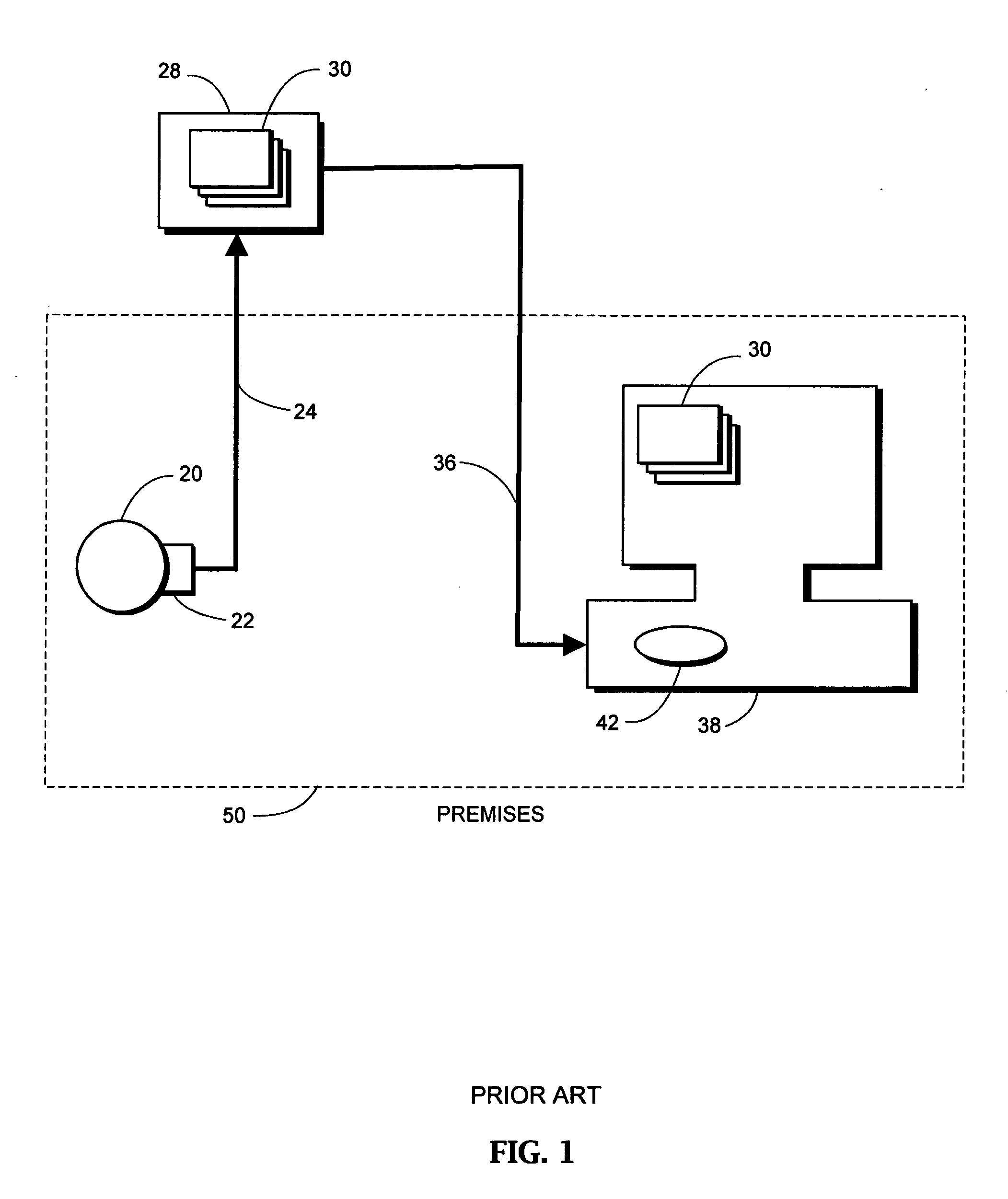
[0051]FIG. 1 is a block diagram illustrating the principle of an Internet-based energy information system that represents certain implementations of prior art, particularly those that are suitable for the application of the method for providing comprehensive electrical usage and demand data of the present invention. The premises 50 and the elements within it represent one of a plurality of similar premises occupied by utility customers who are served by the information system. An electric meter 20 measures the quantity of electrical energy used within the premises. A meter communication portal 22 is contained within the meter 20, or operatively connected to it, so as to communicate usage data through the first network 24 to the utility's data server 28. The data typically consist of the energy usage for each of a consecutive series of time intervals, which have a known correlation with local clock tim...


PUM


Abstract

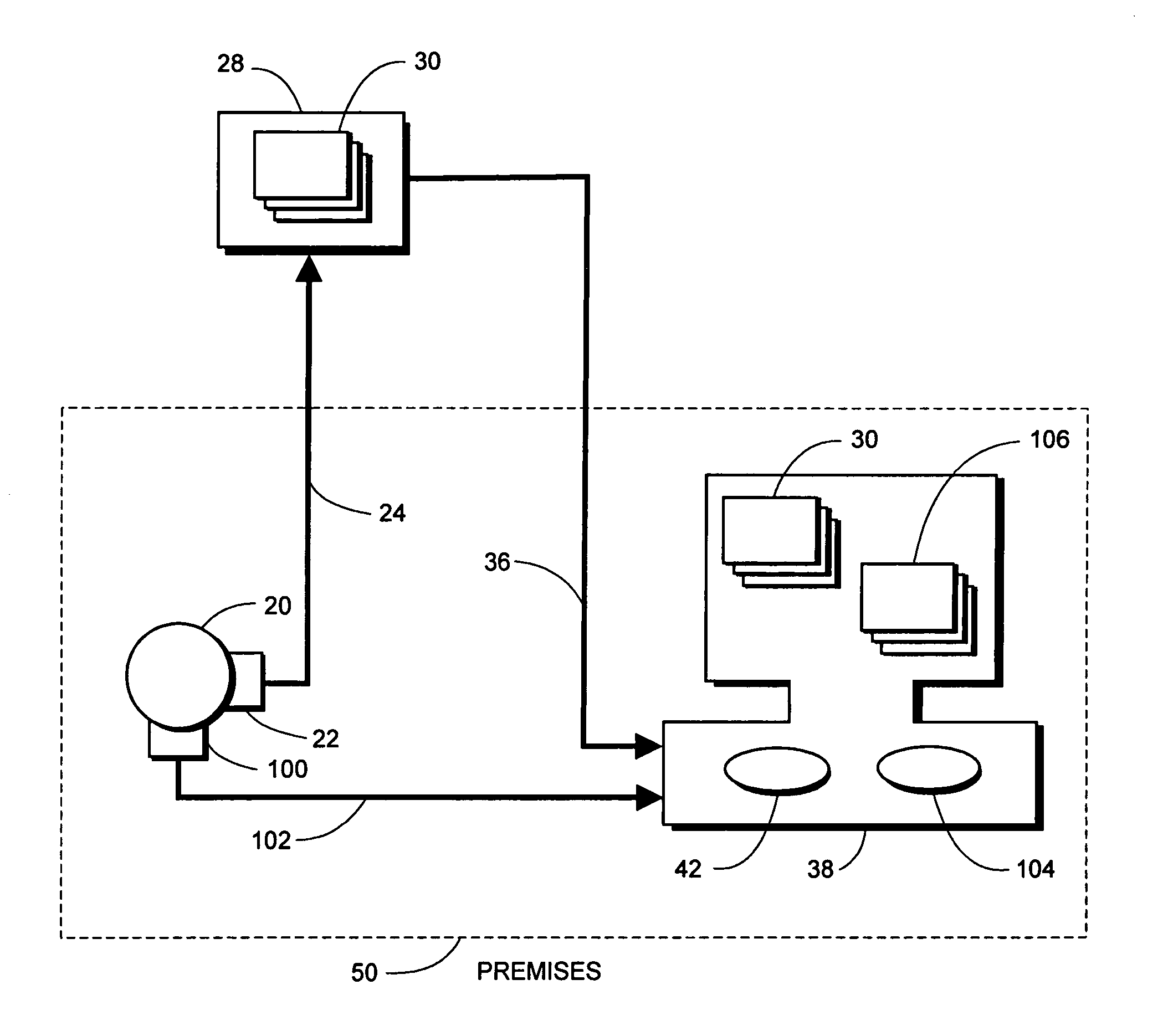
A method for providing comprehensive electrical usage and demand data is disclosed. An electric meter (20), central data server (28), and customer's computer (38) comprise an Internet-based energy information system according to certain of the prior art. It is assumed that either or both of the networks (24, 36) of this system are intermittently connected, as in a dial-up connection, or are expensive to connect continuously, thereby precluding the presentation of real-time data. The present invention provides continuous, real-time data to a utility customer's computer through a direct, low-latency network (102) to the meter. All data are presented in the form of web pages, and the posted pages (30) and the locally generated pages ( ) are hyperlinked to one another, so that the customer has seamless access to comprehensive usage and demand data thereby, enabling proactive management of energy utilization. Further disclosed is a pulse transponder/logger that implements the system at a site with a pulse-output electric meter. Finally disclosed are algorithms to determine electrical demand trends from pulse streams.

Description

CROSS-REFERENCE TO RELATED APPLICATIONS [0001] This application claims the benefit of provisional patent application Ser. No. 60 / 675,068, filed Apr. 26, 2005 by the present inventor.FEDERALLY SPONSORED RESEARCH [0002] Not Applicable [0003] SEQUENCE LISTING OR PROGRAM [0004] Not Applicable BACKGROUND [0005] 1. Field of Invention [0006] The field of the invention relates generally to the utilization of electrical power, and specifically to providing comprehensive electrical usage and demand data, including real-time data, to utility customers. [0007] 2. Description of Prior Art [0008] The two primary components of electrical bills are usage charges and demand charges. Usage refers to the quantity of electrical energy consumed, and it is measured in kilowatt-hours (kWh). Demand is the rate (that is, the pace) at which energy is consumed, and it is measured in kilowatts (kW). Usage is often metered for each of a sequence of equal metering intervals, usually 15 minutes or one hour long. ...

Claims


Application Information

Patent Timeline
IPC IPC(8): G01R19/00
CPCG06Q50/06G01D4/002Y04S20/42Y02B90/246Y04S20/32Y02B90/241Y02B90/20Y04S20/30
Inventor HOWARD, JOHN E.
Owner HOWARD JOHN E
Why Eureka
Try Eureka