Immunity test system

a test system and immunity technology, applied in the field of immunity test systems, can solve the problems of increased design time, inability to evaluate the immunity of test equipment against interference waves, and increased design time, so as to increase the test accuracy and increase the accuracy of calculation of electric field strength

Inactive Publication Date: 2006-11-30
MASPRODENKOH KK
View PDF8 Cites 3 Cited by
  • Summary
  • Abstract
  • Description
  • Claims
  • Application Information

AI Technical Summary

Benefits of technology

[0009] The present invention has been made in view of the problem mentioned above, and it is an object of the invention to provide an immunity test system to determine immunity of electronic equipment against an interference wave, in which it is possible to obtain a test result that allows evaluation on what level of immunity against an interference wave the electronic equipment has.
[0028] According to the immunity test system configured as above, it may be possible to predetermine the conversion data to be used for calculating the electric field strength of the test wave actually irradiated to the electronic equipment based on the signal level of the transmission signal to the antenna in accordance with actual test conditions before placing the electronic equipment and actually starting an immunity test thereof. This will lead to an increased accuracy in calculation of the electric field strength by the test result storing device, and thus to an increased test accuracy in the immunity test system.

Problems solved by technology

Such a conventional immunity test system, however, does not allow evaluation on what level of immunity against an interference wave test equipment has, while allowing determination on whether or not the test equipment has passed a specific immunity test.
Accordingly, evaluation of immunity of test equipment against an interference wave usually takes time and trouble.
This leads to a problem, for example, that to offer electronic equipment having a sufficient immunity against an interference wave, an increased design time and thus an increased cost of the electronic equipment are required.

Method used


Image

  • Immunity test system
  • Immunity test system
  • Immunity test system

Examples


Embodiment Construction

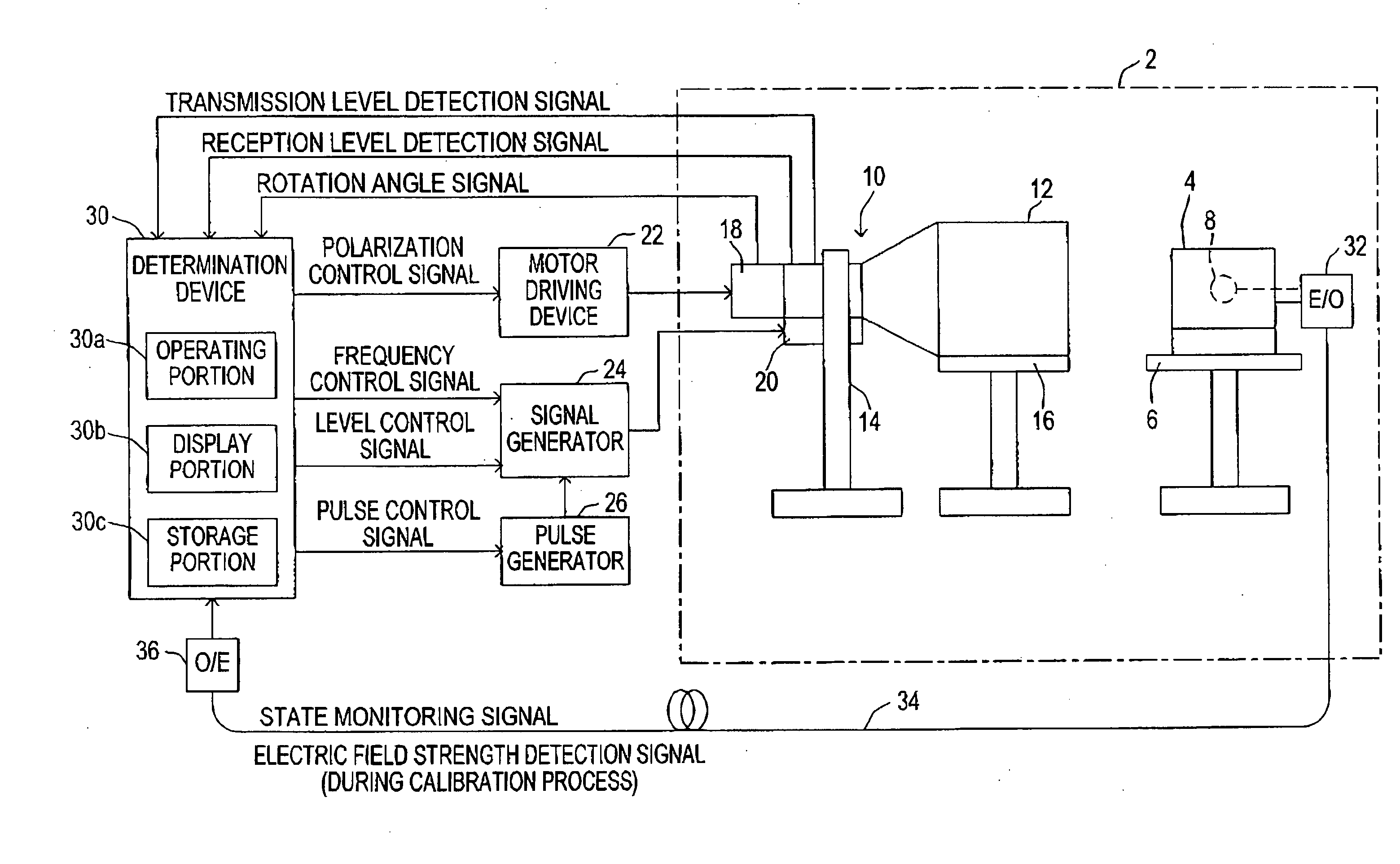
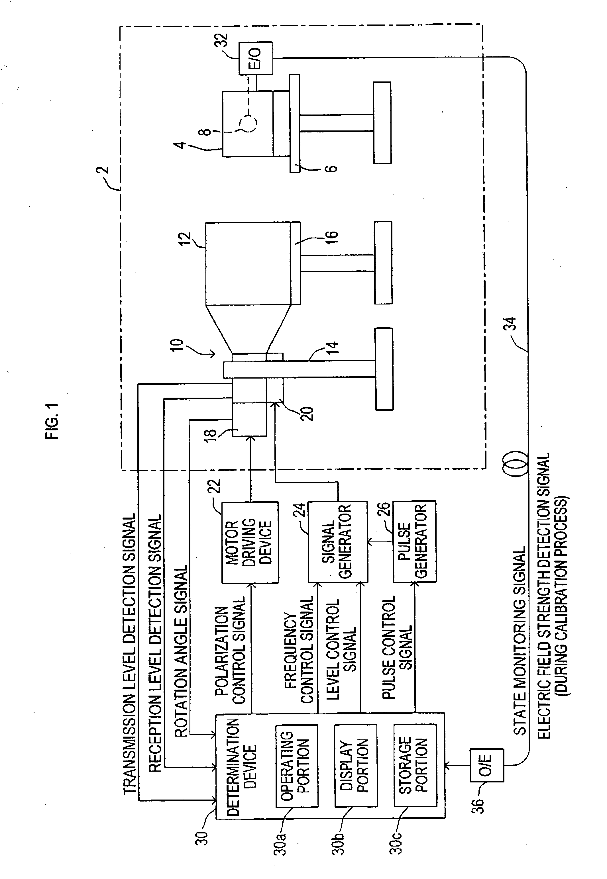
[0039] As shown in FIG. 1, an immunity test system of the present embodiment is designed to be used to conduct an immunity test, in which a test wave as an interference wave is irradiated to test equipment 4 placed on a placement table 6, thereby to determine immunity of the test equipment 4 against the interference wave. The immunity test system includes a horn antenna 10 to emit the test wave and a waveguide 12 to efficiently guide the test wave irradiated from the horn antenna 10 to the test equipment 4.

[0040] The horn antenna 10 and the waveguide 12, as well as the placement table 6 for the test equipment 4, are placed in a radio anechoic chamber 2. The horn antenna 10 is fixed to a support 14 such that an opening face of the horn antenna 10 is directed to the test equipment 4 on the placement table 6. The waveguide 12 is disposed between the horn antenna 10 and the test equipment 4 through a support table 16.

[0041] The horn antenna 10 is provided integrally with an amplifier ...


PUM


Abstract

In an immunity test system of the present invention, a boundary point detection device changes a signal level of a transmission signal input to an antenna through a level adjusting device while monitoring an operation of an electronic equipment, and thereby detects a signal level of the transmission signal at a boundary point, at which the electronic equipment is changed from a normal operation state to an abnormal operation state, or vice versa, due to the test wave; and a test result storing device calculates an electric field strength of the test wave at the boundary point by using conversion data based on the signal level of the transmission signal at the boundary point detected by the boundary point detection device, and stores in a storage device a calculation result of the electric field strength as well as a test condition used for obtaining the electric field strength.

Description

BACKGROUND OF THE INVENTION [0001] (i) Field of the Invention [0002] The present invention relates to an immunity test system for use in conducting an immunity test, i.e., an interference elimination ability test, to determine immunity of electronic equipment by using an interference wave. [0003] (ii) Background Art [0004] There has been a known immunity test to determine immunity of electronic equipment by using an interference wave, as one of EMC (Electro-Magnetic Compatibility) tests for evaluating electromagnetic compatibility of electronic equipment. [0005] The immunity test is a test to determine whether or not electronic equipment as a test object (hereinafter also referred to as “test equipment”) can operate normally when irradiated with an interference wave. The frequency and the strength of the interference wave to be irradiated to the test equipment in the test are defined by international standards by, for example, the International Electrotechnical Commission (IEC), or ...

Claims


Application Information

Patent Timeline
IPC IPC(8): G01R27/28
CPCG01R31/002G01R29/0871
Inventor SUGIURA, TOSHIHIRO
Owner MASPRODENKOH KK
Why Eureka
Try Eureka