In-line optical isolator

a technology of optical isolators and isolators, which is applied in the field of optical isolators, can solve the problems of reducing the size of the optical isolator, degenerating adhesives, and changing characteristics, and achieves the effect of substantially eliminating the dispersion of polarization modes and increasing the optical signal path

Inactive Publication Date: 2006-11-30
OSAKI ELECTRIC CO LTD
View PDF10 Cites 7 Cited by
  • Summary
  • Abstract
  • Description
  • Claims
  • Application Information

AI Technical Summary

Benefits of technology

[0036] According to this configuration, an optical signal that is input from the input optical fiber is separated at the polarization separation device into an ordinary ray and an extraordinary ray in directions that are perpendicular to the plane including the optical axes of the ordinary ray and the extraordinary ray and parallel with these optical axes and, on the side of the light collecting means facing the polarization plane rotating device, optical axes of the ordinary ray and the extraordinary ray are substantially parallel with the focusing central optical axis of the light collecting means and positioned at a substantially equal distance from the focusing central optical axis. Also, the optical axes of the ordinary ray and the extraordinary ray of the reflected optical signal reflected by the reflecting means, on the side of the light collecting means facing the polarization plane rotating device, are also substantially parallel with the focusing central optical axis and positioned at a substantially equal distance from the focusing central optical axis and, at the polarization separation device, the ordinary ray and the extraordinary ray recombine in a direction that is perpendicular to the plane including the optical axes of the input optical fiber and the output optical fiber and parallel with these optical axes. Thus, there is substantially no difference in optical path lengths between the ordinary ray and the extraordinary ray propagating to the polarization separation device, where recombination occurs, and the occurrence of polarization mode dispersion can be substantially eliminated. Therefore, there will be substantially no difference between the ordinary ray and the extraordinary ray in the time required to propagate to the polarization separation device. Thus, there will be no constraint when applying this in-line optical isolator in high-speed optical transmission equipment, such as the number of units that can be used.
[0067] In the in-line optical isolator according to the present invention, there is substantially no difference in the optical path lengths between the ordinary ray and the extraordinary ray propagating to the polarization separation device where recombination occurs, and occurrence of polarization mode dispersion can be substantially eliminated. Therefore, there will be substantially no difference between the ordinary ray and the extraordinary ray in the time required to propagate to the polarization separation device. Thus, there will be no constraint when applying this in-line optical isolator in high-speed optical transmission equipment, such as the number of units that can be used. Also, the number of optical signal paths can be adjusted by only changing the number of pairs of optical fibers, without changing the functional components that perform common functions in multiple optical isolators. Thus, a compact, polarization-independent multifiber in-line optical isolator can be provided, which does not require a lot of time and effort to increase the optical signal paths.

Problems solved by technology

However, the polarization-independent optical isolator disclosed in Patent Literature 1 has four problems, which are described below.
This will result in constraints when applying this optical isolator to high-speed optical transmission equipment with transmission rates of 10 [Gb / s] or higher, such as the number of optical isolators that can be used.
Therefore, it was difficult to reduce the size of the optical isolator.
Due to this difference in propagation time, there will be constraints when applying this optical isolator to high-speed optical transmission equipment with transmission rates of 10 [Gb / s] or higher, such as the number of optical isolators that can be used.
As a result, at the fixed adhesion interface between the Faraday rotator and the adjacent rod lens or the reflecting mirror, adhesive degenerate due to rise in temperature and its characteristics change in some cases.
As a result, conventional optical isolator arrays also have tended to be large in size.
Also, to increase the number of input / output ports, polarizing plate (PR) must be replaced to meet the increase in the number of ports, which requires time and effort.

Method used


Image

  • In-line optical isolator
  • In-line optical isolator
  • In-line optical isolator

Examples


first embodiment

[0085] Next, the present invention is described, where an in-line optical isolator according to the present invention is applied to a fiber-optic communication system.

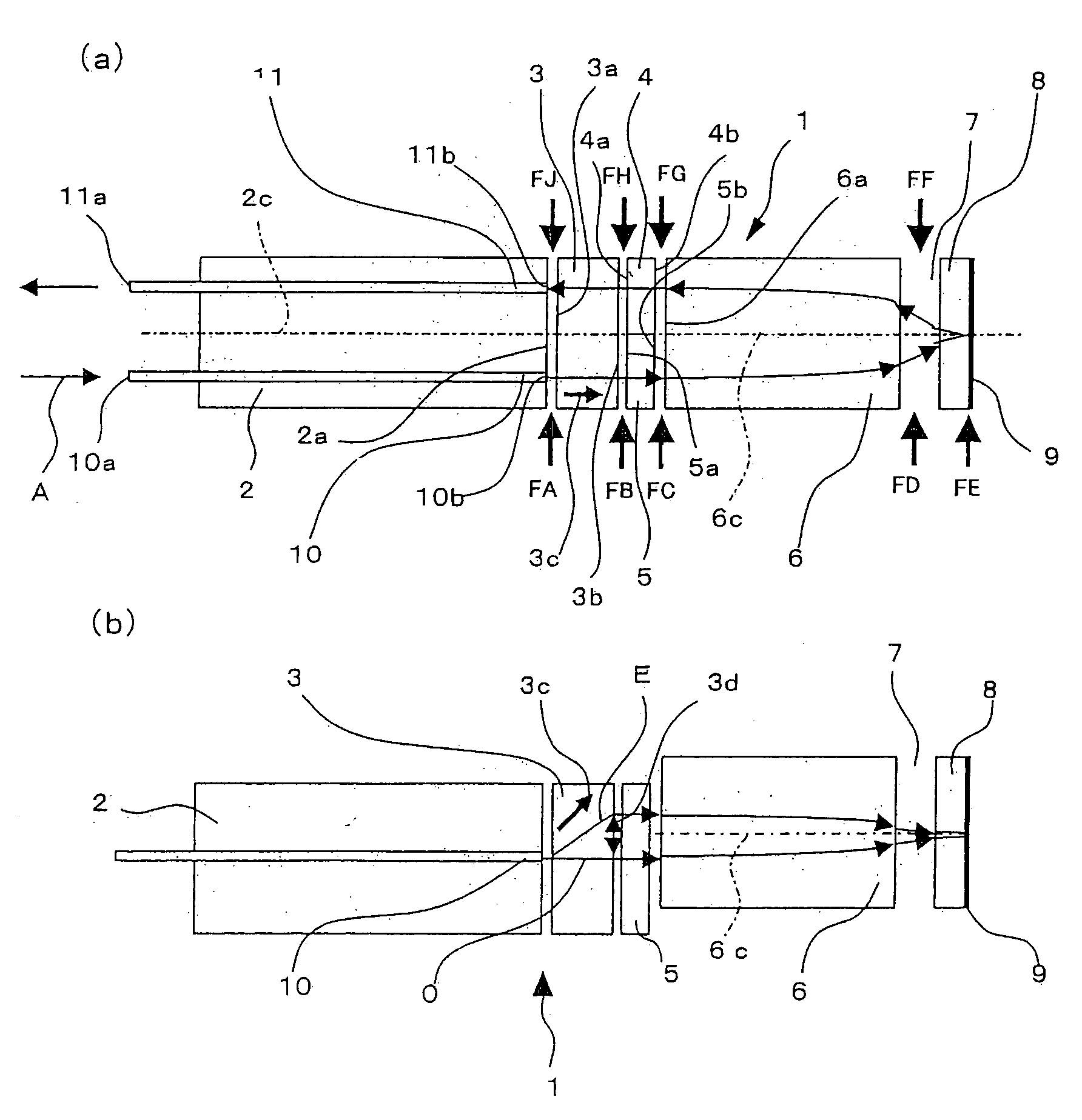
[0086]FIG. 1(a) is the plan view of an in-line optical isolator (1) according to this embodiment and FIG. 1(b) is the side view. The in-line optical isolator (1) is configured with the following elements arranged in the stated order: an optical fiber array (2), a rutile crystal (3), a quartz glass plate (4) and a half-wave plate (5), a focusing rod lens (6), an air gap (7), a magnetized garnet crystal (8) and a total reflecting mirror (9).

[0087] In the optical fiber array (2), optical fibers (10, 11) whose optical axes are parallel with each other, are arranged in parallel and integrated at an interval of 125 [μm]. Optical fibers (10, 11) comprise an input optical fiber that inputs a forward optical signal and an output optical fiber that outputs the forward optical signals that is input from the input optical fiber (...

second embodiment

[0115] Next, the second embodiment is described, where an in-line optical isolator according to the present invention is applied to a fiber-optic communication system.

[0116]FIG. 5(a) is the plan view of an in-line optical isolator (20) according to this embodiment of the present invention and FIG. 5(b) is the side view. In the following description of the in-line optical isolator (20) according to this embodiment, the constituent elements that are identical or equivalent to the constituent elements of the in-line optical isolator (1) according to the first embodiment are given the same codes and their descriptions are omitted.

[0117] The in-line optical isolator (20) is configured with the following elements aligned in the stated order: an optical fiber array (22), a rutile crystal (3), a quartz glass plate (4) and a half-wave plate (5), a focusing rod lens (26), an air gap (7), a magnetized garnet crystal (8) and a total reflecting mirror (9). In this embodiment, the end face (22a)...

third embodiment

[0140] Next, the third embodiment is described, where an in-line optical isolator according to the present invention is applied to a fiber-optic communication system.

[0141]FIG. 9(a) is the plan view of a polarization-independent multifiber optical isolator (30) according to this embodiment and FIG. 9(b) is the side view. The polarization-independent multifiber optical isolator (30) is configured with the following elements aligned in the stated order: an optical fiber array (32), a rutile crystal (3), a quartz glass plate (4) and a half-wave plate (5), a focusing rod lens (6), an air gap (7), a magnetized garnet crystal (8) and a total reflecting mirror (9).

[0142] In the optical fiber array (32), two pairs of optical fibers, the optical fibers (10, 11) and the optical fibers (12, 13), whose optical axes are parallel with each other, are arranged in parallel and integrated at equal intervals of 250 [μm] in the same plane. One optical fiber of each pair (10, 12) comprises an input op...


PUM

PropertyMeasurementUnit
rotating anglesaaaaaaaaaa
wavelengthaaaaaaaaaa

Abstract

In conventional optical isolators, an optical signal is dispersed by polarization or the characteristics are varied by heat generation in a garnet crystal. According to the invention, the crystal optical axis (3c) of rutile crystal (3) is oriented so that the separation directions of the ordinary ray (O) and the extraordinary ray (E) are perpendicular to the plane including the optical axes of optical fibers (10, 11). Furthermore, the focusing central optical axis (6c) of a focusing rod lens (6) is arranged parallel with optical axes of the optical fibers (10, 11) and at a substantially equal distance from the four rays, i.e. the ordinary ray (O) and the extraordinary ray (E) propagating along the optical axis of the optical fiber (10) and the ordinary ray (O) and the extraordinary ray (E) propagating along the optical axis of the optical fiber (11). An air gap (7) of about 200 [μm] is provided, as a heat insulating means, between the focusing rod lens (6) and a magnetized garnet crystal (8).

Description

FIELD OF TECHNOLOGY [0001] The present invention relates to optical isolators that are used to isolate transmission of optical signals in the reverse direction in optical signal paths such as optical communication systems and optical sensor systems, in particular, in-line optical isolators in which optical devices are arranged in a straight line, or in-line optical isolators in which multiple optical isolator functions are integrated. BACKGROUND OF THE INVENTION [0002] In general, in-line optical isolators are used in optical communication systems and optical sensor systems to prevent the reflected optical signal of transmitted optical signals from being input into the signal processing parts of optical transmission equipment. Because the state of polarization of transmitted optical signals normally does not stay constant, a polarization-independent optical isolator is required. [0003] Conventionally, optical isolators of this type include, for example, a polarization-independent op...

Claims


Application Information

Patent Timeline
Patent Type & Authority Applications(United States)
IPC IPC(8): G02B5/30G02B27/28G02B6/26G02F1/09
CPCG02F1/093G02B6/2746G02B27/28
Inventor TAKEUCHI, YOSHIAKIWATANABE, MASARUFUKUZAKI, IKUO
Owner OSAKI ELECTRIC CO LTD
Why Eureka
Try Eureka