Eureka AIR delivers breakthrough ideas for toughest innovation challenges, trusted by R&D personnel around the world.

Circuit assembly and flat display having the same

Inactive Publication Date: 2006-11-30
SAMSUNG SDI CO LTD
View PDF12 Cites 25 Cited by
  • Summary
  • Abstract
  • Description
  • Claims
  • Application Information

AI Technical Summary

Benefits of technology

[0017] It is a feature of an embodiment of the present invention to provide a circuit assembly including a heat sink and a noise isolator, having a heat dissipating function, mounted on the heat sink, so as to improve heat dissipating efficiency and reduce noise.
[0018] It is another feature of an embodiment of the present invention to provide a flat display which has a display driving circuit assembly including a heat sink and a noise isolator having a heat dissipating function to be mounted on the heat sink, so as to improve heat dissipating efficiency and reduce noise.

Problems solved by technology

Specifically, a large amount of energy is required for the excitation of the stable elements, i.e., the discharge gases, to the discharge UV light.
The display driving signals having the high voltages may impose a burden on the display driving circuits formed on the PCB, as well as on the electrodes formed on the panel.
Thus, the display driving signals may cause the electrodes and the display driving circuits to vibrate, and, thus, generate heat and noise.
The vibration and the noise may have an adverse effect on the quality of the PDP.
Further, heat is a main factor that damages elements driving the PDP.
This makes the IPM generate a large amount of heat.
This heat may cause the elements to malfunction and to be damaged.
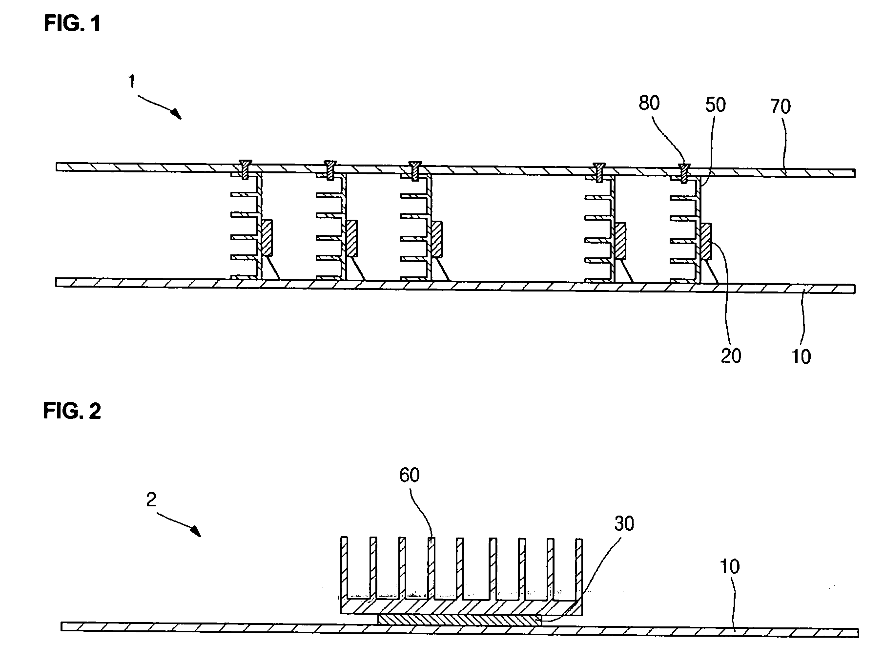
However, it is difficult to attach a noise isolator which reduces noise and improves heat dissipation to the heat sink 60.

Method used


Image

  • Circuit assembly and flat display having the same
  • Circuit assembly and flat display having the same
  • Circuit assembly and flat display having the same

Examples


first embodiment

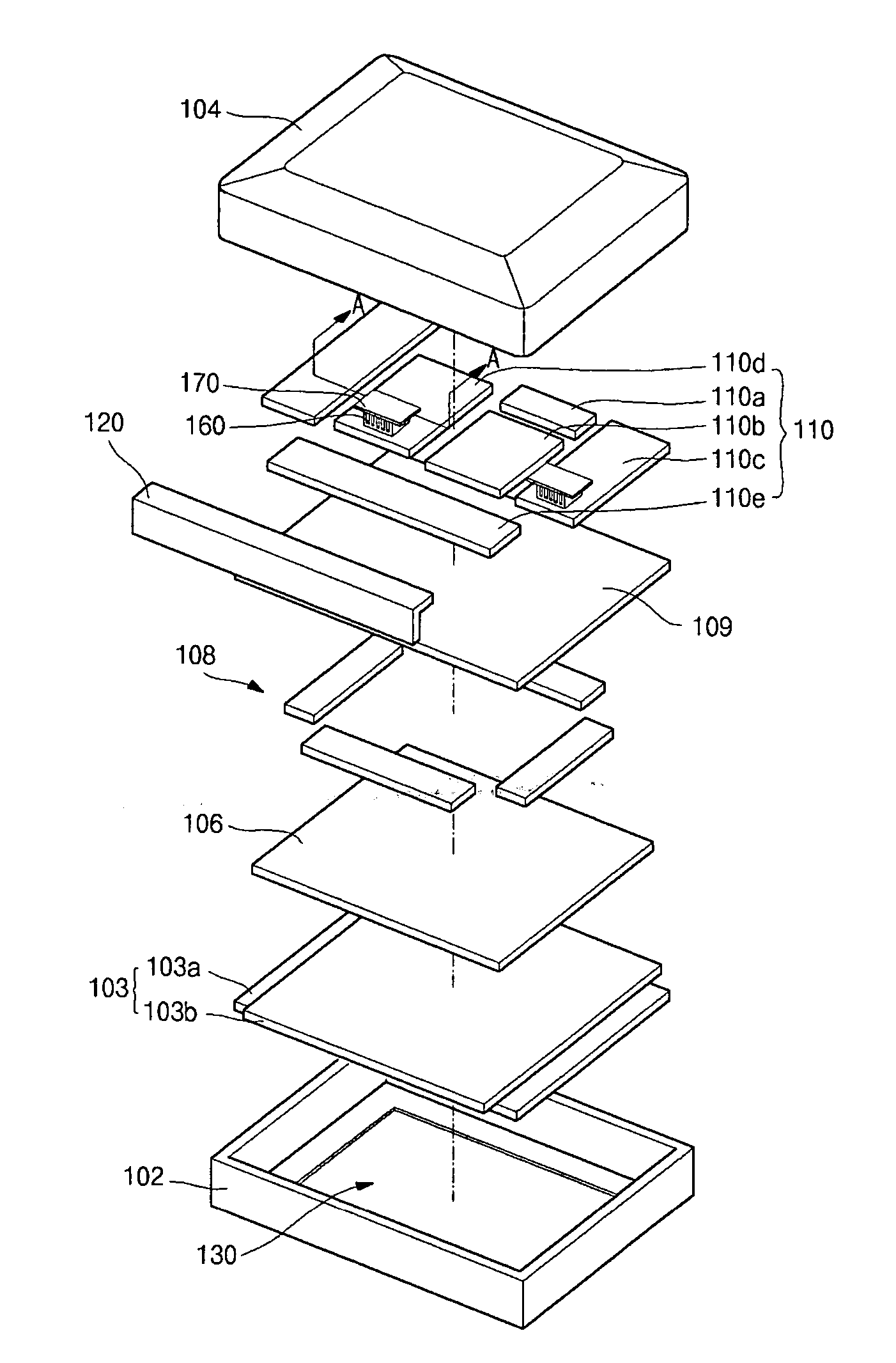
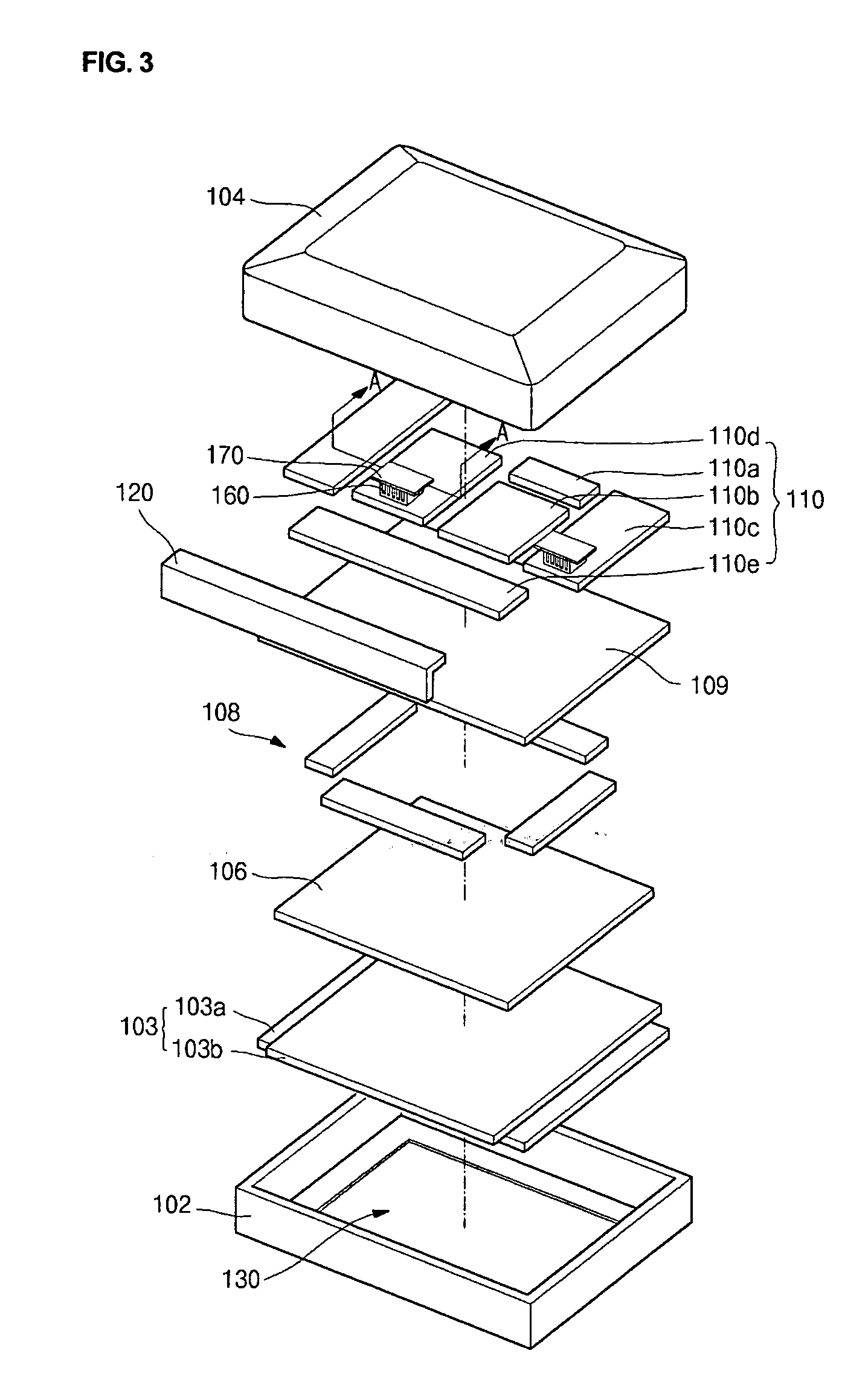
[0037]FIG. 3 illustrates an exploded perspective view of a flat panel display having a display drive circuit assembly according to the present invention.

[0038] Referring to FIG. 3, the display may include a front case 102, a back case 104, a panel 103, a heat conductive sheet 106, an adhesive member 108, a frame 109, a PCB assembly 110, a protective plate 120, a heat sink 160 and a noise isolator 170.

[0039] The front case 102 may be coupled to the back case 104 to protect the panel 103, the heat conductive sheet 106, the adhesive member 108, the frame 109, the PCB assembly 110, etc., therein from exterior contaminants and various impacts. Further, the front case 102 may prevent noise and vibration generated during an operation of the panel from being transmitted to a user. The frame 109 may have flanges (not shown), and the front case 102 may be coupled to the frame 109 through the flanges to more securely attach the heat conductive sheet 106, the adhesive member 108 and the panel ...

second embodiment

[0063]FIG. 5 illustrates a cross-sectional view of a display driving circuit board having an IPM according to the present invention.

[0064] Referring to FIG. 5, the circuit assembly 100′ may include a heat sink 160′ having an extension portion 164′ having a plurality of fins 164a′ and bent fins 164b′. The fins 164a′ may be spaced apart from the noise isolator 170 and arranged between the both bent fins 164b′. This arrangement may allow the heat sink 160′ to obtain a chimney effect, since both bent fins 164b′ are longer than the remaining fins 164a′, increasing a cooling efficiency for the circuit element.

[0065] The circuit assembly 100′ shown in FIG. 5 may have the same elements and members as those of the circuit assembly 100 of FIG. 4, except for the heat sink 160′. Therefore, the description of the structural elements and members of the circuit assembly 100′ will be omitted.

third embodiment

[0066]FIG. 6 illustrates a cross-sectional view of a circuit assembly 100′ having an IPM according to the present invention. Referring to FIG. 6, a heat sink 160″ of the circuit assembly 100″ may include a plurality of heat dissipating fins 168 in parallel with an upper surface of the circuit board 150 and a fixture 166 for fixing the fins 168 parallel with one another.

[0067] The fixture 166 may be positioned at a center portion of the heat dissipating fins 168 to be perpendicular to the fins 168. Therefore, the heat sink 160″ may have a sectional shape similar to the Chinese character . Since a top fin of the heat sink 160″ is parallel with the upper surface of the circuit element 150, the noise isolator 170 can be easily coupled to the heat sink 160″. In FIG. 6, the noise isolator 170 may be coupled to the fixture 166 of the heat sink 160″ by a coupling member 180, e.g., a screw, or by any appropriate securing mechanism.

[0068] The heat sink 160″ may include an extension (not show...


PUM


Abstract

A circuit assembly includes a mount having a circuit element mounted thereon; a heat sink for absorbing and discharging heat generated from the circuit element around, the heat sink mounted on the circuit element on a surface opposite the mount and a noise isolator for isolating noise generated from the circuit board, the noise isolator mounted on the heat sink. The heat sink may include a base portion in surface contact with the circuit element and a top portion in surface contact with the noise isolator. A plurality of fins may be positioned between and parallel to the base and top portions. A plurality of fins may be positioned between and perpendicular to the base and top portions. The top portion may be co-extensive with the base portion, or may only extend past the base portion.

Description

BACKGROUND OF THE INVENTION [0001] 1. Field of the Invention [0002] The present invention relates to a flat display. More particularly the present invention relates to a circuit assembly, and a flat display having the circuit assembly, which includes a heat sink and a noise isolator, which also dissipates heat, mounted on the heat sink, so as to improve heat dissipating efficiency and reduce noise. [0003] 2. Description of the Prior Art [0004] Flat displays have been developed as substitutes for cathode ray tubes. Such flat displays include a liquid crystal display (LCD), an electro-luminescence display (ELD), a field emission display (FED) and a plasma display panel (PDP). [0005] A PDP can display images using plasma discharge, and provides a complete digitalization and a large screen compared to that of other flat displays. The PDP may include front and back cases, a filter assembly, a panel, a heat conductive sheet, a frame, printed circuit boards (PCBs) and additional members wh...

Claims


Application Information

Patent Timeline
IPC IPC(8): H05K7/20
CPCH05K7/20963H05K2201/066H01J11/34H01J2211/62
Inventor JEONG, KWANG JIN
Owner SAMSUNG SDI CO LTD
Why Eureka
Eureka Blog
Learn More