Canted coil spring power terminal and sequence connection system

a technology of power terminals and coil springs, applied in the direction of coupling contact members, coupling device connections, contact member manufacturing, etc., can solve the problems of high cost of machining in producing each prior coil spring terminal, high manufacturing cost, and high overall dimensions of connectors, so as to eliminate the possibility of high voltage electrocution and increase safety

Inactive Publication Date: 2006-11-30
AEES INC
View PDF32 Cites 73 Cited by
  • Summary
  • Abstract
  • Description
  • Claims
  • Application Information

AI Technical Summary

Benefits of technology

[0025] In the above described electrical power system, the irreversible engagement sequence ensures that the positive male terminal between adjacent battery modules in series engagement is not exposed. The incorporation of the sequence tab in combination with an insulative cap positioned atop the first positive male terminal of the first battery module in the assembling sequence substantially eliminates the possibility of high voltage electrocution during assembling and servicing of battery modules that are in series connection.
[0026] The insulative cap is positioned on the upper most portion of the inserting portion of ...

Problems solved by technology

The incorporation of the additional plastic interlocking structures to the exterior of the terminals disadvantageously increases the overall dimensions of the connectors.
The increased dimensions of connectors having additional interlocking structures presents a number of design challenges for integration of the connectors into higher current electronics requiring increased electrical connector density.
The cost of the machining in producing each of the prior coil spring terminals is high.
These processes cause a variety of manufacturing obstacles and safety concerns.
Welding cell to cell connections presents a number of obstacles in manufacturing and servicing.
Welding introduces elevated temperatures to the battery cell, which can damage the battery cell.
In certain battery types, such as Lithium Ion batteries, the elevated temperatures associated with welding may be the source of an explosion.
Further, when utilized in hybrid electrical vehicle applications, welded cell to cell battery packs are not economical to replace, since welded cells are not serviceable during manufacturing or during consumer maintenance.
Module to module conn...

Method used


Image

  • Canted coil spring power terminal and sequence connection system
  • Canted coil spring power terminal and sequence connection system
  • Canted coil spring power terminal and sequence connection system

Examples


Embodiment Construction

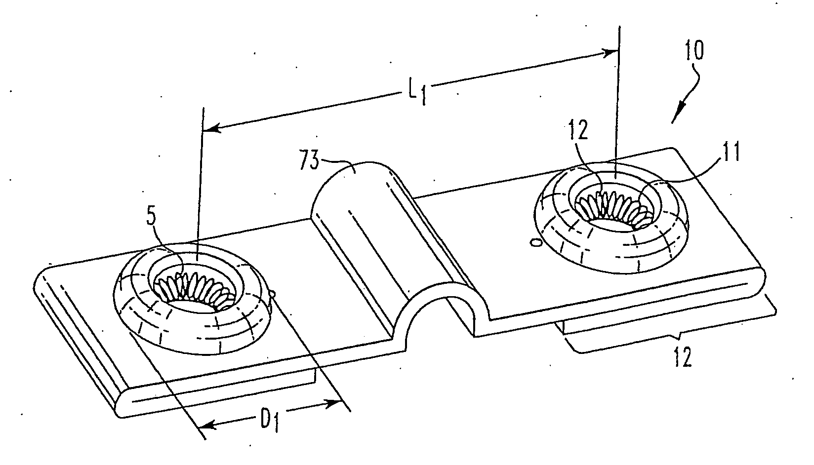
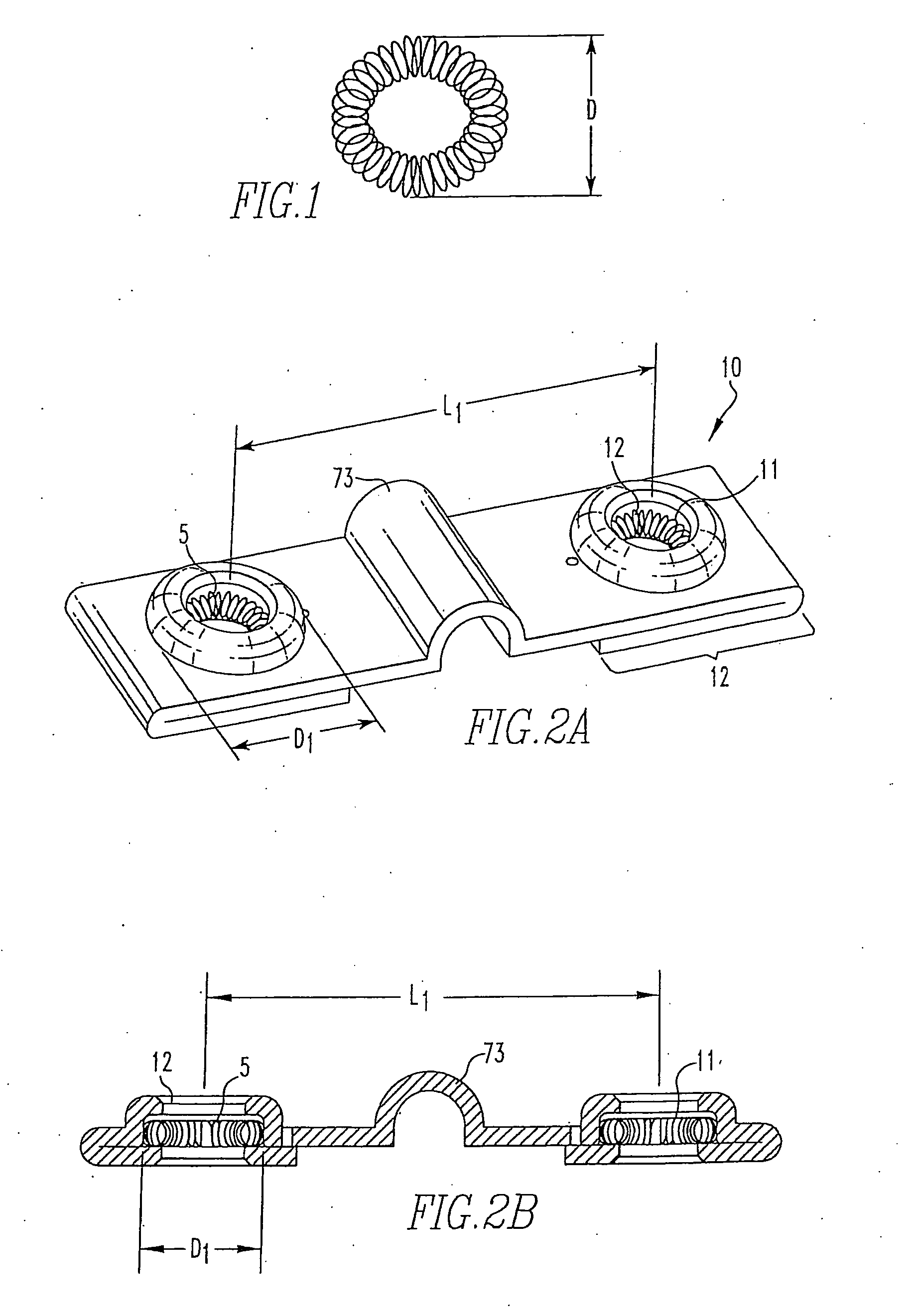
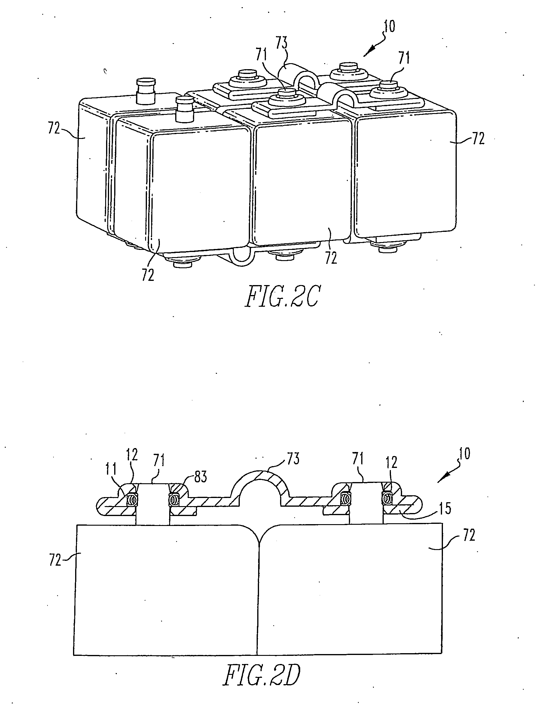
[0056] An electrical terminal system suitable for high current applications, wherein electrical communication between the inserting portion of a male terminal body and a female terminal body is provided by a coil spring positioned within a groove stamped into the female terminal body and means for manufacturing an electrical terminal system, in which a coil spring is positioned within a groove that is stamped into the female connector body. The present invention further provides an electrical connection system for cell to cell battery connections having increased reliability, safety and serviceability. Also provided is a female terminal body for engaging a pin having a coil spring positioned in stamped groove, wherein the female terminal body provides for engagement to at least one wire. An electrical connection system including the terminals for modular batteries provides increased reliability, safety and serviceability. The present invention is now discussed in more detail referri...


PUM


Abstract

The present invention provides an electrical terminal for electrical connections formed from a metal stamping and including a coil spring interface. Broadly, the inventive electrical terminal includes a female terminal body having at least one opening for receiving an inserting portion of a male terminal body, the female terminal body including a stamped groove positioned about a perimeter of the opening; and a coil spring for providing an electrical interface between the inserting portion of the male terminal body and the female terminal body being positioned in the stamped groove.

Description

CROSS REFERENCE TO RELATED APPLICATIONS [0001] This application is a continuation-in-part and claims the benefit of U.S. patent application Ser. No. 11 / 137,289, filed on May 25, 2005, the disclosure of which is fully incorporated by reference herein.FIELD OF THE INVENTION [0002] The present invention relates to high current electrical connections, in which electrical communication between male and female terminals is provided by a coil spring interface. BACKGROUND OF THE INVENTION [0003] Male and female terminals in high current electrical connection systems are currently locked by terminals incorporating exterior plastic interlocking structures. The incorporation of the additional plastic interlocking structures to the exterior of the terminals disadvantageously increases the overall dimensions of the connectors. The increased dimensions of connectors having additional interlocking structures presents a number of design challenges for integration of the connectors into higher curre...

Claims


Application Information

Patent Timeline
IPC IPC(8): H01R24/00
CPCH01R4/184H01R4/188H01R43/16H01R13/03H01R13/187H01R11/28
Inventor ZHAO, WEIPINGSPADONI, STEFANOBAGCHI, ANKOOR
Owner AEES INC
Why Eureka
Try Eureka