Control apparatus and control method of vehicular driving apparatus

a technology of control apparatus and control method, which is applied in the direction of electric propulsion mounting, electric control, machines/engines, etc., can solve the problems of energy loss associated with and achieve the effects of reducing the amount of energy lost, and reducing the use of the second driving power sour

Inactive Publication Date: 2006-11-30
TOYOTA JIDOSHA KK
View PDF8 Cites 45 Cited by
  • Summary
  • Abstract
  • Description
  • Claims
  • Application Information

AI Technical Summary

Benefits of technology

[0010] Preferably, in a second aspect of the invention, the second driving power source controller does not perform assist for the engine in the output of driving power through the use of the second driving power source, if the emission gas recirculation amount provided by the emission gas recirculation device is greater than or equal to a second emission gas recirculation amount that is set greater than the first emission gas recirculation amount. Due to this arrangement, in a low load state of the engine where the emission gas recirculation amount provided by the emission gas recirculation device is basically large, the energy loss associated with the use of the second driving power source disappears.
[0011] Furthermore, in a third aspect of the invention, (a) a control apparatus of a vehicular driving apparatus includes an engine as a driving power source, a second driving power source that assists the engine in output of driving power, and an emission gas recirculation device that recirculates a portion of an emission gas of the engine to an intake system, and (b) the control apparatus also includes a second driving power source controller that assists the engine in the output of driving power through the use of the second driving power source so that an emission gas recirculation rate provided by the emission gas recirculation device becomes greater than or equal to a first emission gas recirculation rate that is set based on a load state of the engine.
[0012] The assist for the engine in the output of driving power is performed by the second driving power source controller through the use of the second driving power source so that the emission gas recirculation rate provided by the emission gas recirculation device becomes greater than or equal to the first emission gas recirculation rate. Hence, it becomes possible to put the engine in a low load state where the emission gas recirculation rate, which decreases as the engine shifts to higher load states, is greater than or equal to the first emission gas recirculation rate. In other words, by expanding the regions where the emission gas recirculation rate greater than or equal to the first emission gas recirculation rate is effected by putting the engine in a low load state, degradation of emission gas is curbed. Furthermore, since the assist for the engine in the output of driving power is performed by the second driving power source controller through the use of the second driving power source, the output necessary to run the vehicle can be secured even if the engine is put in a low load state.
[0013] Preferably, in a fourth aspect of the invention, the second driving power source controller does not perform assist for the engine in the output of driving power through the use of the second driving power source, if the emission gas recirculation rate provided by the emission gas recirculation device is greater than or equal to a second emission gas recirculation rate that is set greater than the first emission gas recirculat

Problems solved by technology

Due to this arrangement, in a low load state of the engine where the emission gas recirculation amount provided by the emission g

Method used


Image

  • Control apparatus and control method of vehicular driving apparatus
  • Control apparatus and control method of vehicular driving apparatus
  • Control apparatus and control method of vehicular driving apparatus

Examples


Embodiment Construction

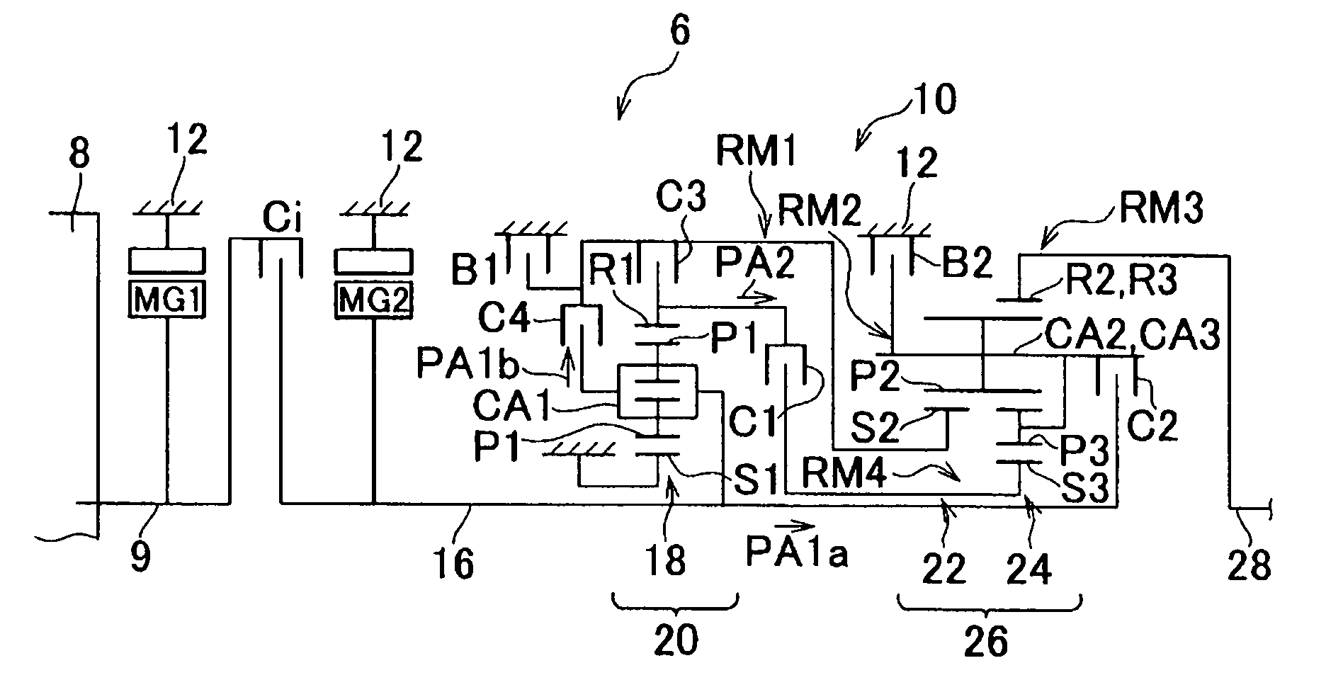
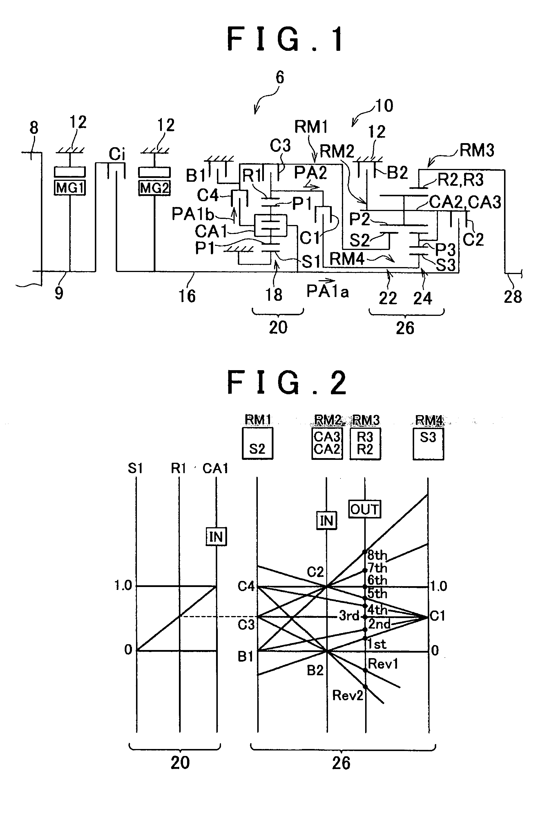
[0041]FIG. 1 is a diagram illustrating the construction of a vehicular driving apparatus (hereinafter, referred to as “driving apparatus”) 6 provided in a vehicle to which the invention is applied. The driving apparatus 6 is made up of a transmission case 12 provided as a non-rotational member attached to a vehicle body, and a first motor-generator MG1 as a first electric motor, a lockup clutch Ci, a second motor-generator MG2 as a second electric motor, and a stepped automatic transmission (hereinafter, referred to as “automatic transmission”) 10 which are sequentially disposed about a common axis in the transmission case 12. This automatic transmission 10 is made up of an input shaft 16 that is mechanically coupled to a crankshaft 9 of a diesel engine (hereinafter, referred to as “engine”) 8 as a driving power source exclusively via the lockup clutch Ci, a first speed changer portion 20 constructed mainly of a first planetary gear set 18, a second speed changer portion 26 construc...


PUM


Abstract

A control apparatus/method curbs the degradation of emission gas, for a vehicular driving apparatus including an engine and a second driving power source that assists the engine in the output of driving power. Torque assist is executed by a hybrid controller through the use of a first motor-generator and/or the second motor-generator so that the EGR rate achieved by an EGR device becomes greater than or equal to an EGR rate threshold value (first EGR rate) determined on the basis of the load state of an engine. Therefore, it becomes possible to put the engine in a low load state where the EGR rate, which decreases as the engine shifts to higher load states, is greater than or equal to the EGR rate threshold value.

Description

INCORPORATION BY REFERENCE [0001] The disclosure of Japanese Patent Application No. 2005-156479 filed on May 27, 2005, including the specification, drawings and abstract is incorporated herein by reference in its entirety. BACKGROUND OF THE INVENTION [0002] 1. Field of the Invention [0003] The invention relates to a control apparatus / method of a vehicular driving apparatus comprising an engine and a second driving power source that assists the engine in the output of driving power. More particularly, the invention relates to a technology of controlling the load state of the engine in order to curb degradation of the emission gas. [0004] 2. Description of the Related Art [0005] Vehicles equipped with an emission gas recirculation device, a so-called EGR device, which refluxes a portion of the emission gas of an engine, such as a diesel engine or the like, to the intake system, that is, recirculates it to the intake system in order to reduce the amount of emission of NOx (oxides of ni...

Claims


Application Information

Patent Timeline
IPC IPC(8): B60K1/02F02M25/07F02B47/08B60K6/442B60K6/547B60L50/16B60W10/04B60W10/06B60W10/08B60W10/10B60W20/00F02D41/02
CPCB60K6/442Y10T477/23B60W10/06B60W10/08B60W10/115B60W20/00F02D41/0072F02D2250/24F02D2250/41F02M25/0707F02M25/0774F02M25/078Y02T10/54Y02T10/6234Y02T10/6286Y02T10/47Y10S903/911B60W10/02F02M26/55F02M26/60F02M26/05Y02T10/40Y02T10/62B60W20/15B60W20/10
Inventor KAMADA, ATSUSHITABATA, ATSUSHI
Owner TOYOTA JIDOSHA KK
Why Eureka
Try Eureka