Deformable tools and implants

a tool and tool body technology, applied in the field of tools and implants, can solve the problems of pain, disfiguring fractures, distortion and shortening of the spine, and pain of spinal compression fractures, and achieve the effect of increasing the dimension

Inactive Publication Date: 2006-11-30
ORTHOPHOENIX
View PDF99 Cites 427 Cited by
  • Summary
  • Abstract
  • Description
  • Claims
  • Application Information

AI Technical Summary

Benefits of technology

[0008] An aspect of some embodiments of the invention relates to a method of treating a vertebra in which a plastic (e.g., polymeric, non-metallic) deformer is inserted into the vertebra and deformed to have an increased dimension in the axis of the spine, without use of inflation via fluid injection or absorbing. In an exemplary embodiment of the invention, the deformer is deformer by applying force (e.g., a compression force) thereto. In another embodiment, the deformer is released to retain an original configuration thereof. In an exemplary embodiment of the invention, a kit including a suitably sized deformer and a spinal delivery system, is pr

Problems solved by technology

Spinal compression fractures are painful and disfiguring fractures in which a spinal vertebra axiall

Method used


Image

  • Deformable tools and implants
  • Deformable tools and implants
  • Deformable tools and implants

Examples


Embodiment Construction

Slotted Tube Expander Design

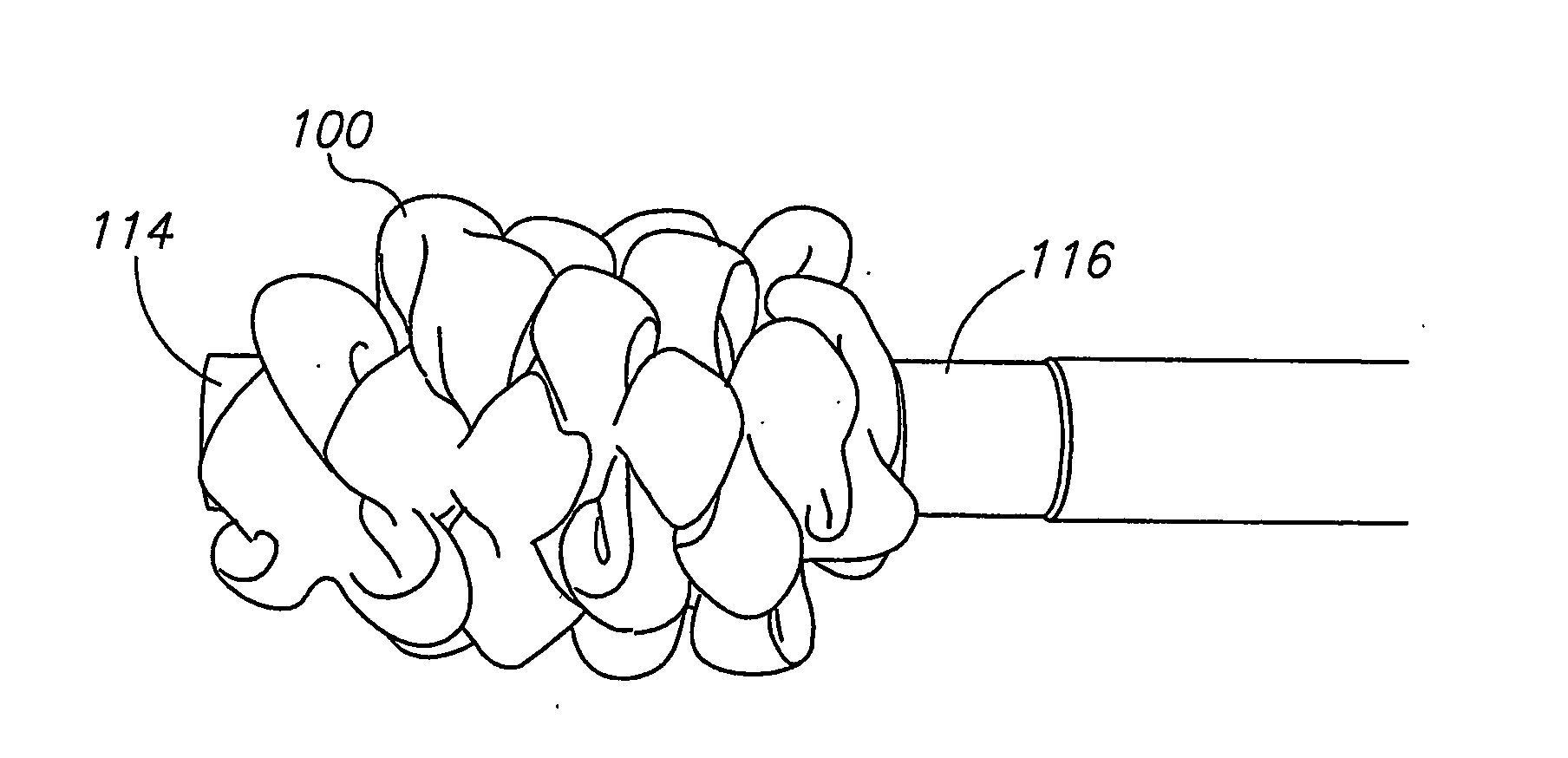
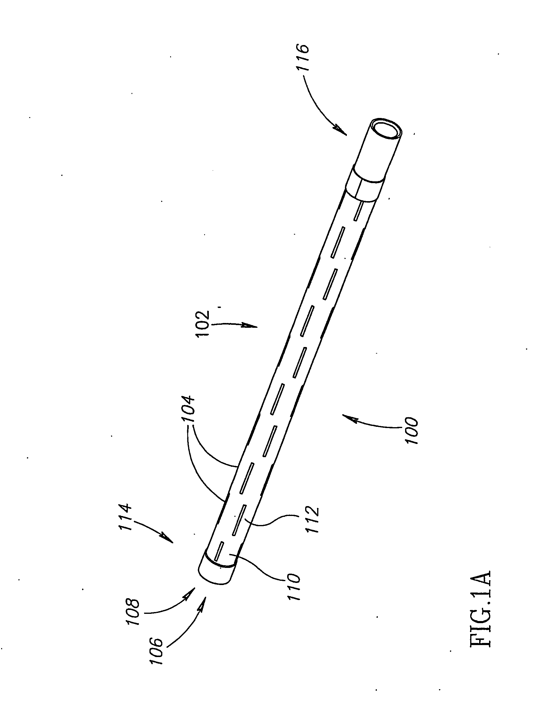
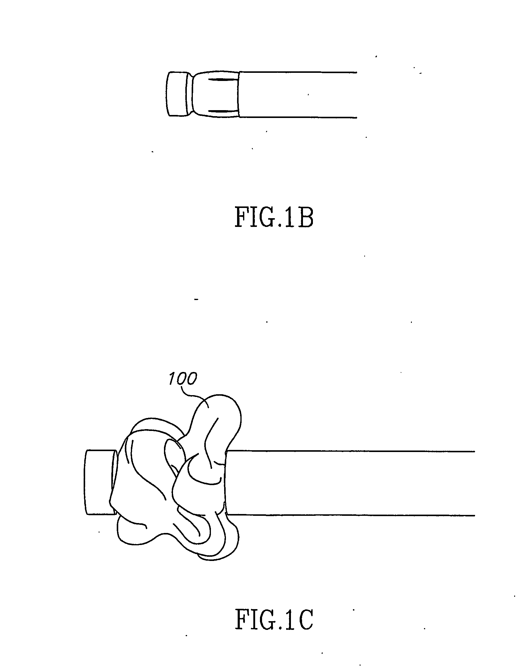
[0139]FIG. 1A is a schematic illustration of an undeformed deformer 100, in accordance with an exemplary embodiment of the invention. FIG. 1F is a schematic illustration of a fully deformed deformer 100, in accordance with an exemplary embodiment of the invention. FIGS. 1B-1E show intermediate states and FIGS. 1G-1H show an undeforming process (described below).

[0140] In this design, deformer 100 comprises a tube body 102, having a plurality of slots 104 formed along its length, in an axial direction. In the embodiment shown, slots 104 are arranged in alternating lines 106 and 108 such that a plurality of alternating leaf lines are formed, comprising leaves 110 alternating (axially and radially) with leaves 112. As will be described below, for example, other designs may be provided. A distal end 114 and a proximal end 116 are also marked on FIG. 1A.

[0141] As can be seen in FIG. 1F, when fully deformed, deformer 100 substantially fills a volume of spac...


PUM


Abstract

A medical grade deformer, comprising: an axial member; and a pliable tube mounted on said axial member and adapted to be deformed from a first, narrower diameter, configuration to a second, greater diameter, configuration.

Description

RELATED APPLICATIONS [0001] The present application claims the benefit under 35 USC 119(e) of U.S. Provisional Applications for patent Ser. No. 60 / 478,841 filed on Jun. 17, 2003, Ser. No. 60 / 529,612 filed on Dec. 16, 2003, Ser. No. 60 / 534,377 filed Jan. 6, 2004 and Ser. No. 60 / 554,558 Mar. 18, 2004, the disclosures of which are incorporated herein by reference. [0002] The present application is a continuation-in-part of U.S. Ser. No. 09 / 890,172 and U.S. Ser. No. 09 / 890,318, the disclosures of which are incorporated herein by reference. [0003] The present application claims priority from Israel application IL 160987, filed 21 Mar. 2004, the disclosure of which is incorporated wherein by reference.FIELD OF THE INVENTION [0004] The present invention is related to tools and implants which are deformed during use, for example for orthopedic use. BACKGROUND [0005] Spinal compression fractures are painful and disfiguring fractures in which a spinal vertebra axially compresses. This causes ...

Claims


Application Information

Patent Timeline
IPC IPC(8): A61B17/68A61B17/00A61B17/70A61B17/88A61FA61F2/44
CPCA61B1/00071A61B1/00133A61B17/7097A61B17/7098A61B17/7258A61B17/7266A61C8/004A61B17/8855A61B17/8858A61B2017/00004A61B2017/00557A61C8/0033A61B17/742
Inventor BEYAR, MODECHAYSHAVIT, RONENVACHTENBERG, OZGLOBERMAN, ORENSHASHA, URI
Owner ORTHOPHOENIX
Why Eureka
Try Eureka