Closed loop impedance-based cardiac resynchronization therapy systems, devices, and methods

Inactive Publication Date: 2006-11-30
CARDIAC PACEMAKERS INC
View PDF29 Cites 71 Cited by
  • Summary
  • Abstract
  • Description
  • Claims
  • Application Information

AI Technical Summary

Problems solved by technology

Moreover, some patients have poor spatial coordination of heart contractions.
Some patients may have both irregular rhythms and poor spatial coordination of heart contractions.
In either of these cases, diminished blood circulation may result.
One problem faced by physicians treating cardiovascular patients is the treatment of congestive heart failure (also referred to as “CHF”).
The heart consumes more energy and oxygen, and its condition typically worsens over a period of time.
This reduces the pumping efficiency of the heart.
Moreover, in LBBB, for example, different regions within the left ventricle may not contract together in a coordinated fashion.
Such too-fast heart rhythms also cause diminished blood circulation because the heart isn't allowed sufficient time to fill with blood before contracting to expel the blood.
Such pumping by the heart is inefficient.
For example, techniques that detect electrical depolarizations (e.g., QRS complexes) at the left and right sides of the heart to indicate the synchrony between the two sides of the heart are often not a good indicator of the actual mechanical synchrony between left and right ventricular heart contractions.
This adds expense and complexity to an implantable cardiac function management system.
This electrode configuration is practical because it potentially makes use of existing electrodes available with existing leads, however, it may be confounded slightly by other effects, such as right atrial volume fluctuations arising from right atrial contractions.
For this reason, these techniques are also particularly useful for a patient with complete AV block, in which intrinsic electrical signals are not conducted to the ventricles and, therefore, CRT control techniques involving Q

Method used


Image

  • Closed loop impedance-based cardiac resynchronization therapy systems, devices, and methods
  • Closed loop impedance-based cardiac resynchronization therapy systems, devices, and methods
  • Closed loop impedance-based cardiac resynchronization therapy systems, devices, and methods

Examples


example 1

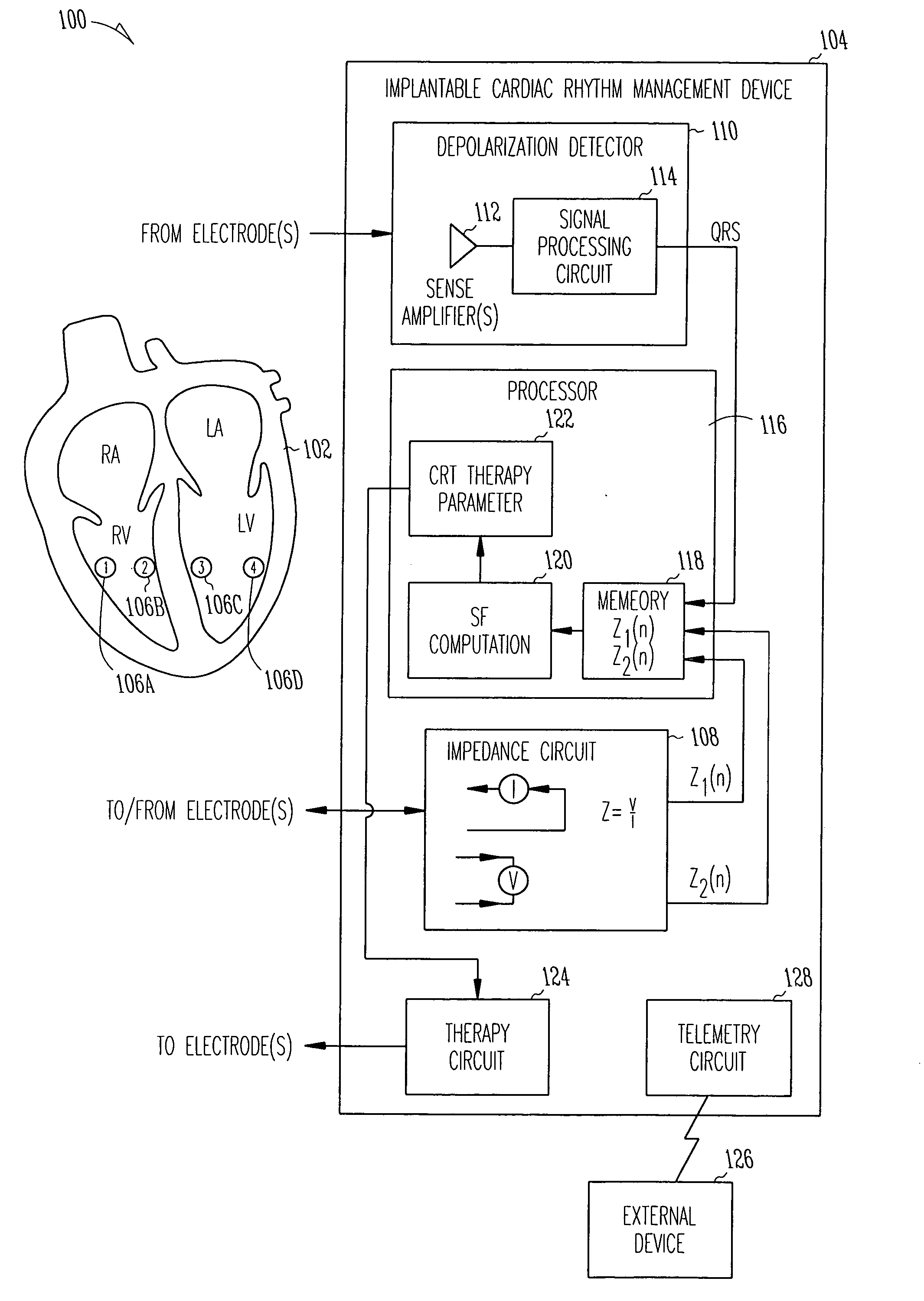
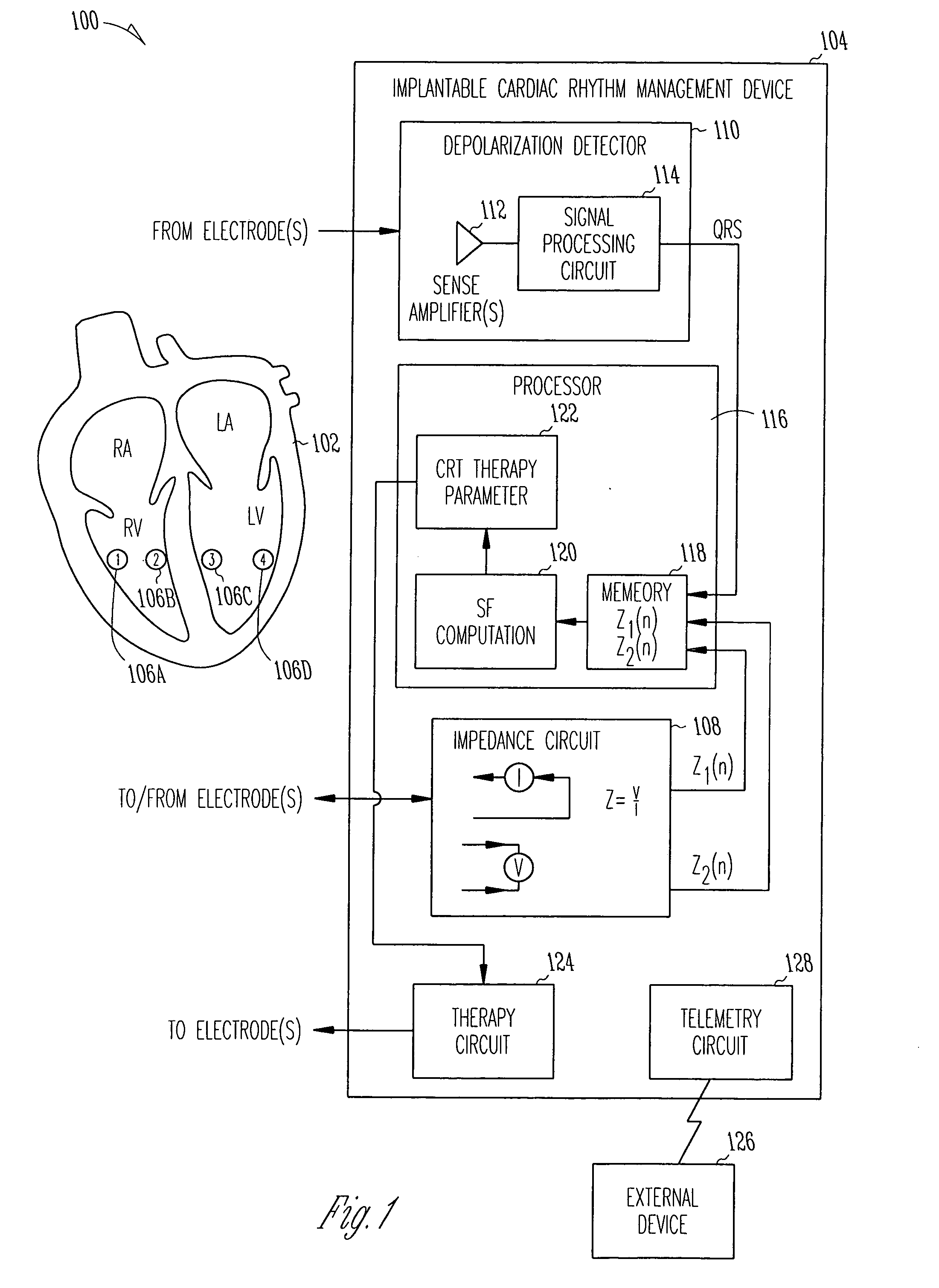
[0040]FIG. 1 is a schematic diagram illustrating generally one example of portions of a system 100 and portions of an environment with which it is used, including a heart 102. In this example, the system 100 includes an implantable cardiac function management device 104. In one example, the device 104 is coupled to the heart 102 using one or more intravascular or other leadwires. The leadwires provide electrodes 106 in association with the heart 102. FIG. 1 illustrates an example that includes a first electrode 106A that is located at or near a right ventricular freewall, a second electrode 106B that is located at or near a right ventricular septum, a third electrode 106C that is located at or near a left ventricular septum, and a fourth electrode 106D that is located at or near a left ventricular freewall. This particular electrode configuration of FIG. 1 is useful for providing conceptual clarity, however, other possibly more practical electrode configurations will be discussed fu...

example 2

[0057]FIG. 6 is a schematic diagram illustrating generally one example of portions of a system 600 and portions of an environment with which it is used, including a heart 602. In this example, the system 600 includes an implantable cardiac function management device 604. In one example, the device 604 is coupled to the heart 602 using one or more intravascular or other leads. The leads provide electrodes 606 in association with the heart 602. FIG. 6 illustrates an example that includes a first electrode 606A that is located at or near an midportion of a right ventricular freewall, a second electrode 606B that is located in association with a left ventricular freewall, such as by being introduced on an intravascular lead that is inserted into coronary sinus 607 toward a coronary sinus vein. A third electrode 606C is located on a hermetically-sealed housing (“can”) of the implantable device 604 (or, alternatively, on an insulating “header” extending from the housing of the implantable...

example 3

[0069]FIG. 10 is a schematic diagram illustrating generally one example of portions of a system 1000 and portions of an environment with which it is used, including a heart 1002. In this example, the system 1000 includes an implantable cardiac function management device 1004. In one example, the device 1004 is coupled to the heart 1002 using one or more intravascular or other leads. The leads provide electrodes 1006 in association with the heart 1002. FIG. 10 illustrates an example that includes a first electrode 1006A that is located at or near a middle or apical portion of a right ventricular septum, a second electrode 1006B that is located in association with a left ventricular freewall, such as by being introduced on an intravascular lead that is inserted into coronary sinus 1007 toward a lateral or posterior coronary sinus vein.

[0070] In FIG. 10, the device 1004 includes an impedance circuit 1008 for measuring a left ventricular impedance between the first electrode 1006A and ...


PUM


Abstract

This document discusses, among other things, systems, devices, and methods measure an impedance and, in response, adjust an atrioventricular (AV) delay or other cardiac resynchronization therapy (CRT) parameter that synchronizes left and right ventricular contractions. A first example uses parameterizes a first ventricular volume against a second ventricular volume during a cardiac cycle, using a loop area to create a synchronization fraction (SF). The CRT parameter is adjusted in closed-loop fashion to increase the SF. A second example measures a septal-freewall phase difference (PD), and adjusts a CRT parameter to decrease the PD. A third example measures a peak-to-peak volume or maximum rate of change in ventricular volume, and adjusts a CRT parameter to increase the peak-to-peak volume or maximum rate of change in the ventricular volume.

Description

CROSS REFERENCE TO RELATED APPLICATIONS [0001] This patent application is a continuation of Jiang Ding et al. U.S. patent application Ser. Number 11 / 136,894, entitled CLOSED LOOP IMPEDANCE-BASED CARDIAC RESYNCHRONIZATION THERAPY SYSTEMS, DEVICES, AND METHODS, filed on May 25, 2005 and assigned to Cardiac Pacemakers, Inc., and which is incorporated by reference in its entirety.TECHNICAL FIELD [0002] This patent document pertains generally to cardiac function management devices, and more particularly, but not by way of limitation, to closed loop resynchronization therapy systems, devices, and methods. BACKGROUND [0003] When functioning properly, the human heart maintains its own intrinsic rhythm. Its sinoatrial node generates intrinsic electrical cardiac signals that depolarize the atria, causing atrial heart contractions. Its atrioventricular node then passes the intrinsic cardiac signal to depolarize the ventricles, causing ventricular heart contractions. These intrinsic cardiac sig...

Claims


Application Information

Patent Timeline
IPC IPC(8): A61N1/362
CPCA61B5/053A61N1/3627A61N1/3684A61N1/3682A61N1/36521A61N1/36842A61N1/36843
Inventor NI, QUANDING, JIANGYU, YINGHONGDAUM, DOUGLAS R.SPINELLI, JULIO C.STAHMANN, JEFFREY E.
Owner CARDIAC PACEMAKERS INC
Why Eureka
Try Eureka