System and method for disaster recovery of data

Active Publication Date: 2006-11-30
HITACHI LTD
View PDF22 Cites 54 Cited by
  • Summary
  • Abstract
  • Description
  • Claims
  • Application Information

AI Technical Summary

Benefits of technology

[0015] As described above, since data status in the remote site can be acquired by the detection

Problems solved by technology

As a method for reducing the line cost, the use of a public line, which is inexpensive but its line quality is not ensured, as a line for the remote copy has been studied.
In the case of the public line, since the line utilization rate changes depending on the end users, the band used in the remote copy cannot be secured.
As a result, there is a possibility that the time required for the remote copy is increased.
Therefore, when the performance of the remo

Method used


Image

  • System and method for disaster recovery of data
  • System and method for disaster recovery of data
  • System and method for disaster recovery of data

Examples


first embodiment

[0029] First, the first embodiment of the present invention will be described with reference to FIG. 1 to FIG. 3.

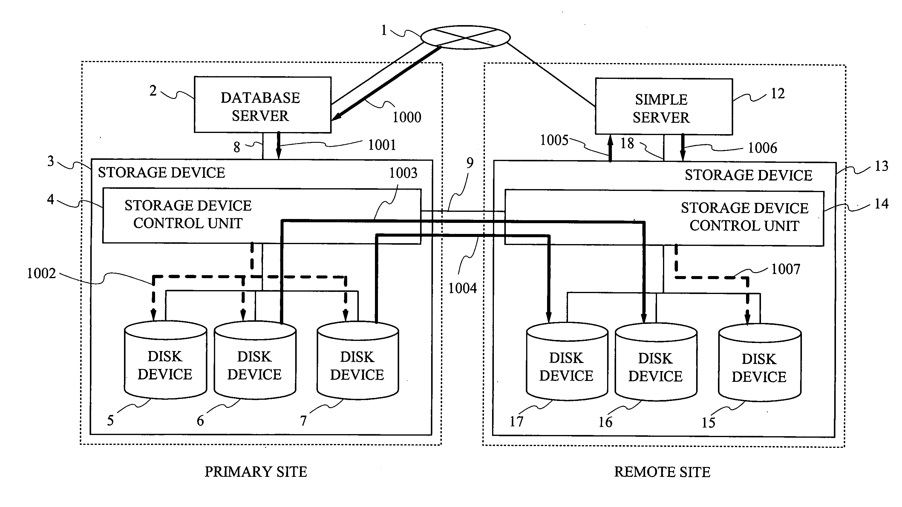
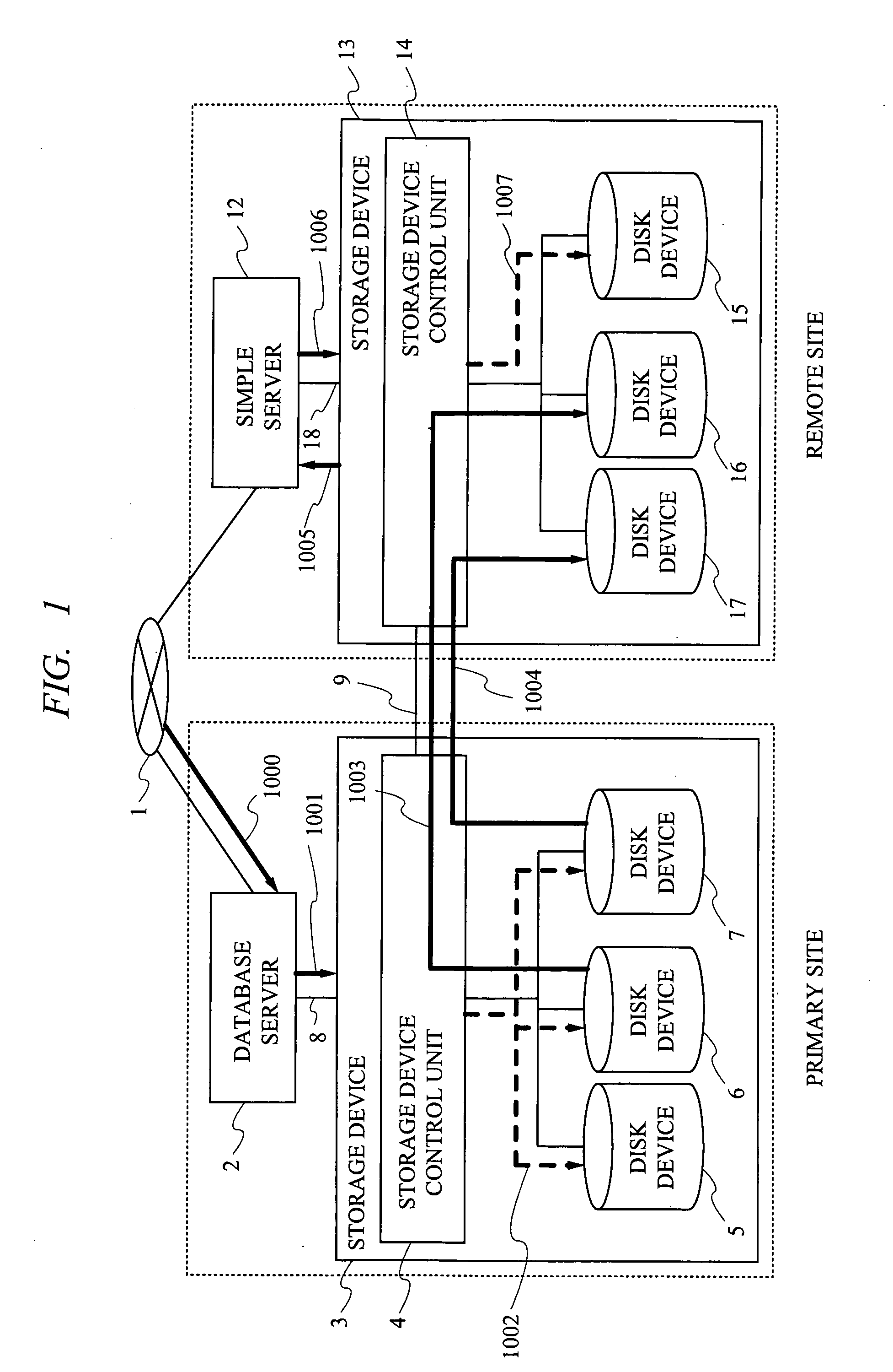
[0030]FIG. 1 shows the brief overview of the first embodiment of the DR system using log synchronous transmission method. In FIG. 1, a primary site is comprised of a database server 2 and a storage device 3. The database server 2 and the storage device 3 are connected by a server / storage connection interface 8. The storage device 3 includes disk devices 5, 6 and 7 in which data to be read and written by a storage device control unit 4 is stored, and the storage device 3 retains the data for online processing received by the database server 2 through an operation network 1, the data required for the processing, and the data executed in the database server 2.

[0031] The database server 2 and the storage device 3 read and write data through the server / storage connection interface 8. In addition, when the change in the disk devices 5, 6 and 7 requested by the database server...

second embodiment

[0108] The DR system using log synchronous transmission method according to the second embodiment will be described below, in which the switch notification of the disk device to which the update log is written is sent between servers.

[0109] In the first embodiment, the switch notification of the disk device to which the update log is written is notified to the remote site by writing it to the log. In this embodiment, however, another switch notification method will be described with reference to FIG. 9.

[0110]FIG. 9 is a block diagram showing an example of the configuration of the DR system using log synchronous transmission method, in which the state of the remote copy function is stored in the transmission information acquisition unit 30 through the communication between servers.

[0111] In this embodiment, after switching the disk device to which the writing of the update log in the primary site is requested, the switch notification signal is sent to the remote site through the o...

third embodiment

[0113] The DR system using log synchronous transmission method according to the third embodiment will be described, in which a broad band line and a narrow band line are provided as the line to connect the storage devices and the lines are switched. However, the broadband line in this case generally indicates the dedicated line with a high transmission rate, and the narrow band line generally indicates the inexpensive public line with a low transmission rate.

[0114] In the first embodiment, the remote copy function is switched so as not to be influenced by the line utilization rate between the storage devices, thereby maintaining the online performance. However, in this embodiment, the method for maintaining the online performance by switching the lines used for the remote copy functions will be described with reference to FIG. 10.

[0115]FIG. 10 is a block diagram showing an example of the configuration of the DR system using log synchronous transmission method, in which the broad b...


PUM


Abstract

When a public line is used for a remote copy function of storage in a disaster recovery (DR) system, the online performance is degraded due to the increase and decrease of the line utilization rate. Therefore, it is desired to change the remote copy function depending on the line utilization rate. Also, there is the possibility of data loss if disaster occurs during the copy between storage devices. Therefore, it is desired to perform the processing to detect the data status immediately before the occurrence of the disaster. By switching the synchronous transmission and the asynchronous transmission in accordance with the increase and decrease of the response time of the remote copy function between storage devices, the online performance of the primary site can be maintained without being influenced by the line utilization rate, and the data loss can be detected based on the used remote copy function.

Description

CROSS-REFERENCE TO RELATED APPLICATION [0001] The present application claims priority from Japanese Patent Application No. JP 2005-158269 filed on May 31, 2005, the content of which is hereby incorporated by reference into this application. TECHNICAL FIELD OF THE INVENTION [0002] The present invention relates to a system and a processing method thereof for reducing the degradation of online performance and for detecting the data loss when a disaster or a failure has occurred in the DR (Disaster Recovery) system in which a database server and a storage are incorporated. BACKGROUND OF THE INVENTION [0003] In recent years, IT has been fundamental to business and taken on a growing importance. Thus, the effect of a system down is enormous. In the case of finance industry, for example, it is reported that the loss due to the system down reaches several million dollars by hour. In such an environment, a disaster recovery (hereinafter referred to as DR) to backup data to a remote site in o...

Claims


Application Information

Patent Timeline
IPC IPC(8): G06F11/00
CPCG06F11/2071G06F11/2066
Inventor MIZUNO, KAZUHIKOFUJIWARA, SHINJISUZUKI, YOSHIO
Owner HITACHI LTD
Why Eureka
Try Eureka