
Electrically actuated flow assisted exhaust valve

a technology of electric actuator and flow assisted exhaust valve, which is applied in the field of flapper valve, can solve the problems of back pressure, increase in actuator noise, and failure to solve the problem of actuation noise, etc., and achieve the effect of improving noise and operational characteristics

Inactive Publication Date: 2006-12-07
ET US HLDG
View PDF8 Cites 52 Cited by
  • Summary
  • Abstract
  • Description
  • Claims
  • Application Information

AI Technical Summary

Benefits of technology

[0012] The subject invention thus provides an exhaust valve with improved noise and operational characteristics. These and other features of the present invention can be best understood from the following specification and drawings, the following of which is a brief description.

Problems solved by technology

Traditionally, both electric and vacuum actuators have had problems with actuation noise, back pressure, and maintaining the flapper valve in an open position under high exhaust flow conditions.
Under high exhaust flow conditions, the flapper valve has a resultant torque that has a tendency to pivot the flapper valve toward the closed position.
One proposed solution involved changing an angle of attack, i.e. the angle from a horizontal position, of the flapper valve when in the open position, however, this solution was unsuccessful.
One disadvantage with this solution is that when the controller determines that the flapper valve should move from the open position toward the closed position, the significant spring force must be overcome, which results in an increase in actuator noise.
Another disadvantage is that amperage and vacuum needed to overcome the spring force must also be increased in operation for both electric and vacuum actuators, respectively.

Method used


Image

  • Electrically actuated flow assisted exhaust valve
  • Electrically actuated flow assisted exhaust valve
  • Electrically actuated flow assisted exhaust valve

Examples


Embodiment Construction

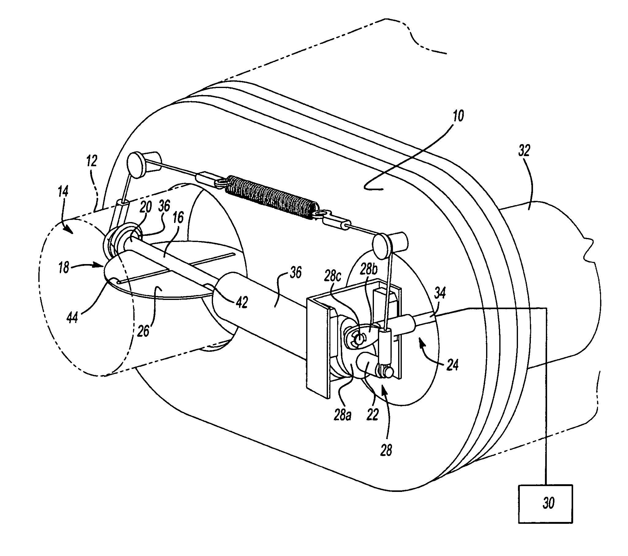
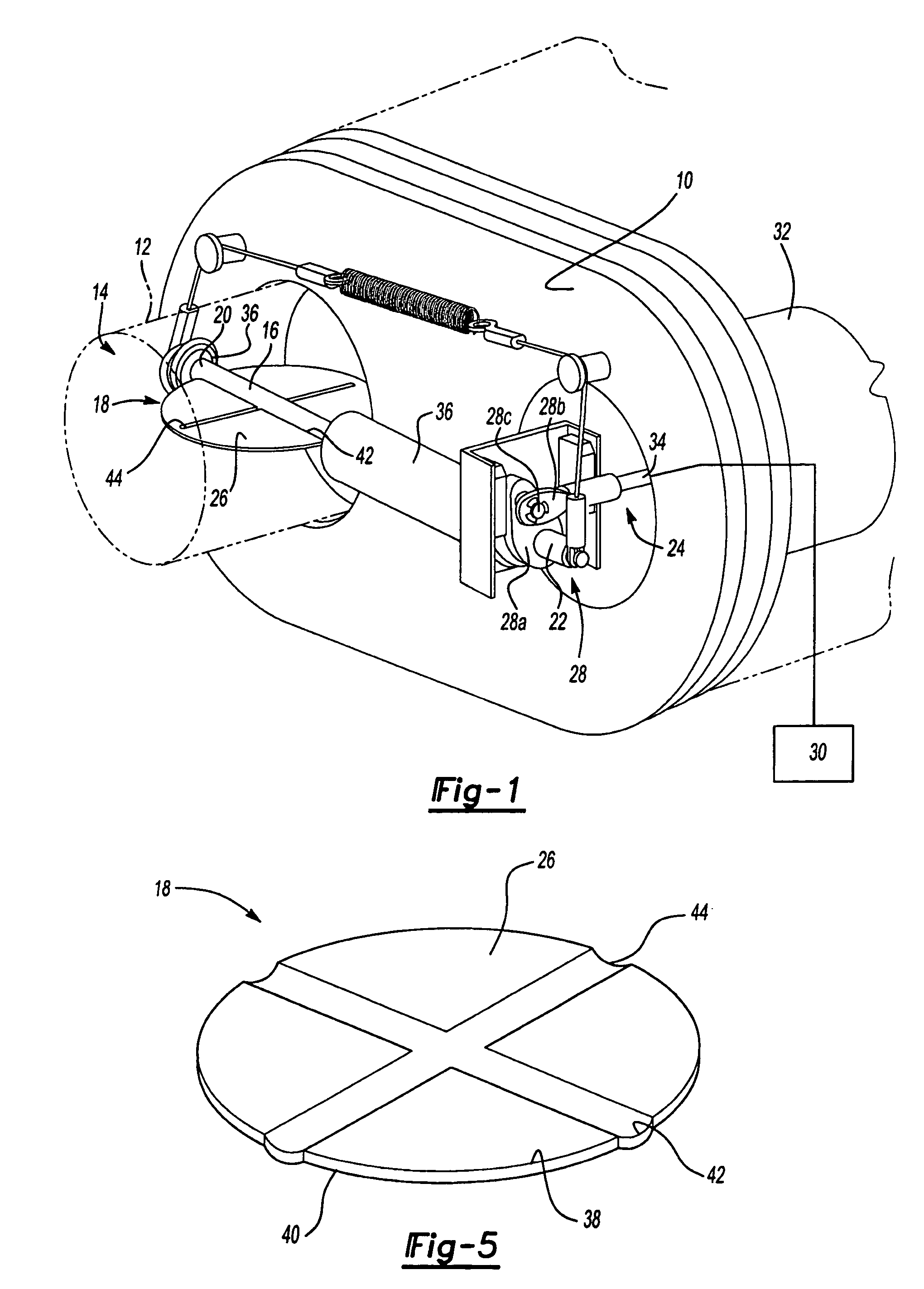
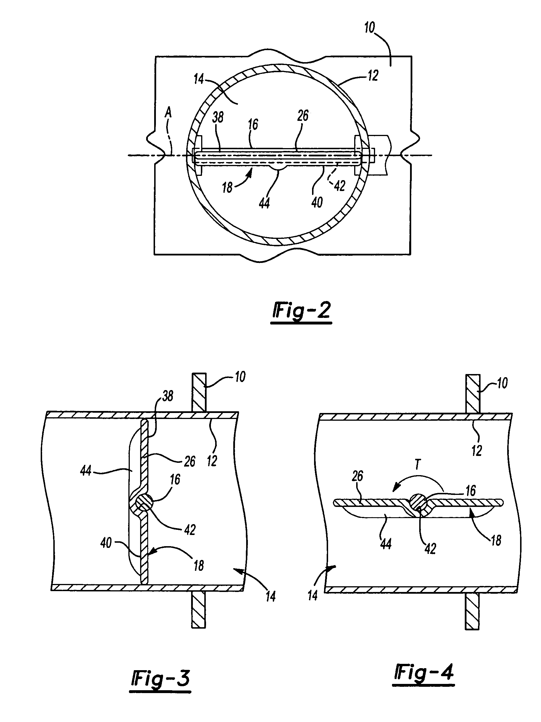
[0024] As shown in FIG. 1, an exhaust system component, such as a muffler, includes a datum plate 10 that supports an inlet tube 12. The inlet tube 12 defines an inner cavity 14 that directs exhaust flow through the exhaust system component. In the example shown in FIG. 1, exhaust flows right to left through the inlet tube 12 and into the muffler. It should be understood that the muffler is just one example of an exhaust system component that benefits from the subject invention detailed below, and that other exhaust system components could also benefit from the subject invention.

[0025] A noise attenuation valve assembly includes a shaft 16 and a flapper valve 18 that is fixed to the shaft 16. Preferably, the shaft 16 and flapper valve 18 are welded together, however, other attachment methods could also be used. The shaft 16 has a first end 20 supported by the inlet tube 12 and a second end 22 that extends out from the inlet tube 12 toward an actuator 24. Each of the first 20 and se...


PUM


Abstract

An exhaust valve includes a flapper valve that is pivotable within an exhaust component between open and closed positions. The flapper valve is supported on a shaft that is coupled to an actuator. The flapper valve comprises a disc-shaped body that is fixed to the support shaft such that the disc-shaped body is asymmetrical about the axis of rotation.

Description

RELATED APPLICATIONS [0001] This application is a continuation-in-part application of PCT / US2005 / 044305 filed on Dec. 28, 2005, which claims priority to U.S. provisional application No. 60 / 642,634, which was filed on Jan. 10, 2005.TECHNICAL FIELD [0002] This invention generally relates to a flapper valve as used in an exhaust system, wherein the flapper valve has improved noise and operational characteristics. BACKGROUND OF THE INVENTION [0003] Noise attenuation valves are often used in vehicle exhaust systems to reduce noise generated during vehicle operation. For example, a noise attenuation valve is incorporated into a muffler to reduce noise generated by a vehicle engine. Traditionally, the noise attenuation valve includes a flapper valve mounted on a shaft that pivots the flapper valve within an inlet tube formed within the muffler. The flapper valve has a disc-shaped body that rotates within the inlet tube to vary exhaust gas flow area. The flapper valve pivots between an open...

Claims


Application Information

Patent Timeline
Patent Type & Authority Applications(United States)
IPC IPC(8): F01N7/00F16K1/22
CPCF01N1/165F01N1/18F01N2290/06F02D9/04F16K1/222F02D9/106F02D9/1065F02D9/107F16K1/221F02D9/1055
Inventor ABRAM, KWINCALLAHAN, JOSEPH
Owner ET US HLDG
Learn More