
Apparatus and method for verifying the volume of liquid dispensed by a liquid-dispensing mechanism

a liquid-dispensing mechanism and apparatus technology, applied in the direction of instruments, ac/dc measuring bridges, laboratory glassware, etc., can solve the problems of verification tools failing to meet requirements, affecting the completion of system checks, and affecting the accuracy of measurement techniques

Inactive Publication Date: 2006-12-07
ABBOTT LAB INC
View PDF41 Cites 5 Cited by
  • Summary
  • Abstract
  • Description
  • Claims
  • Application Information

AI Technical Summary

Benefits of technology

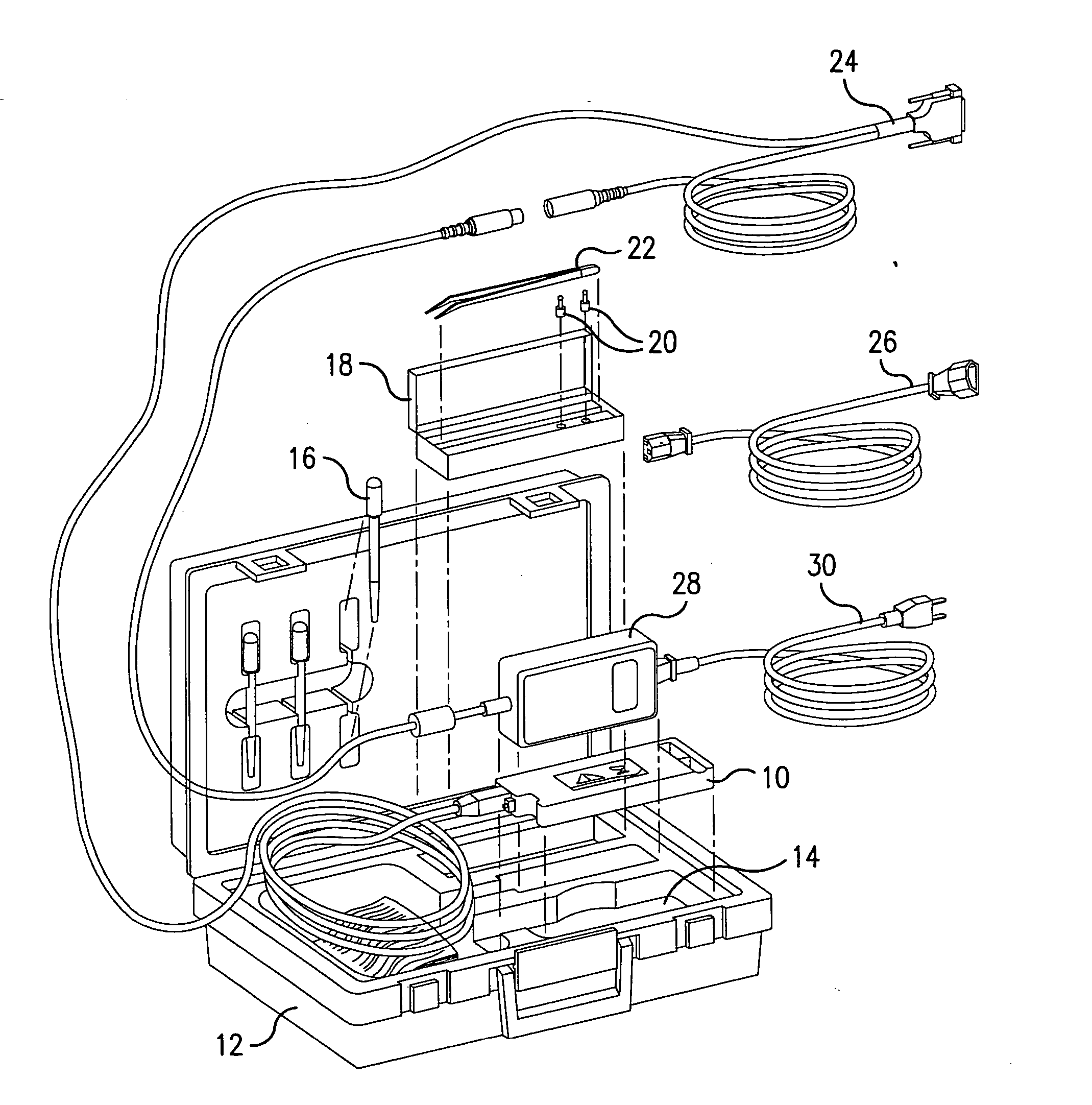
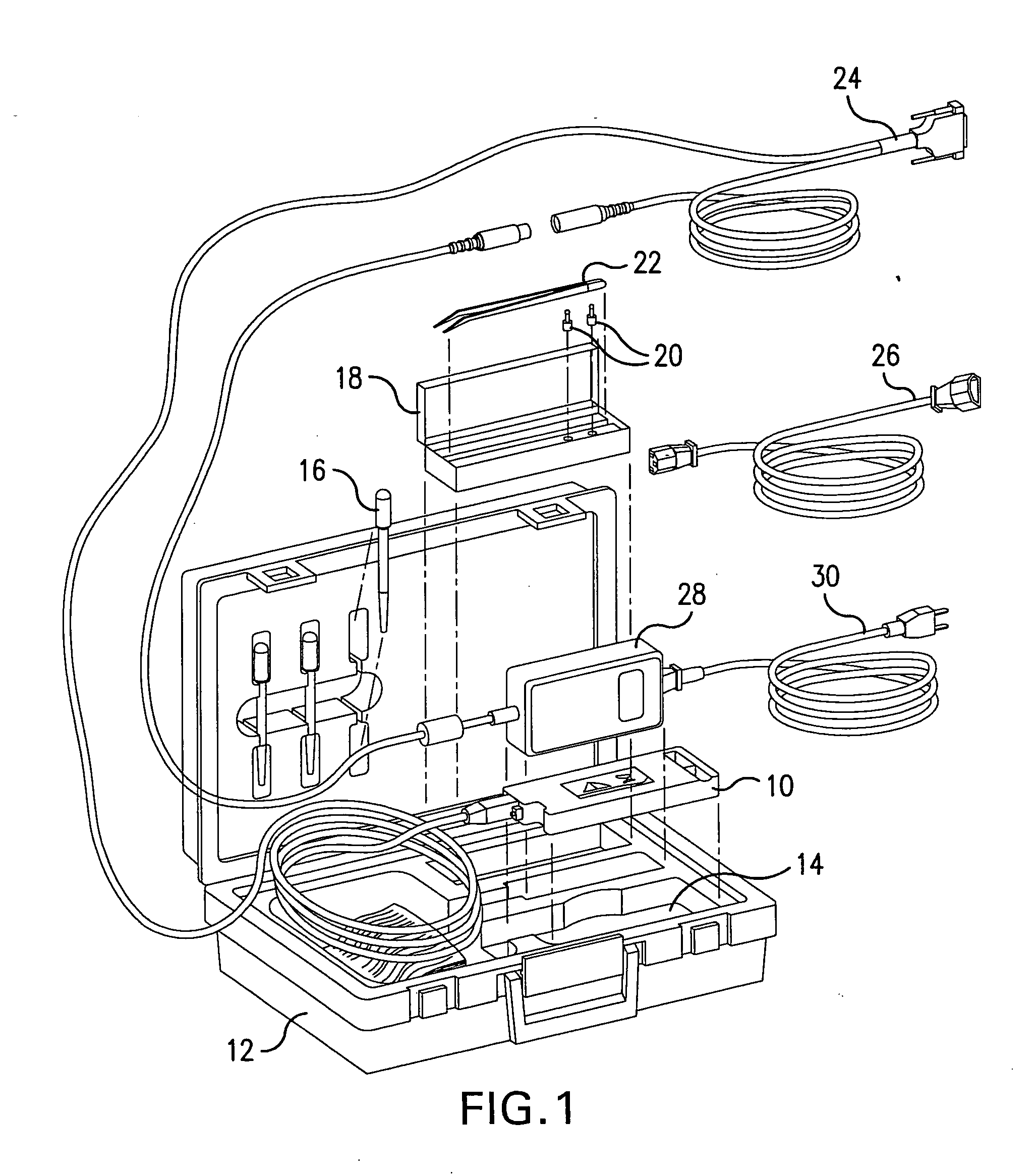
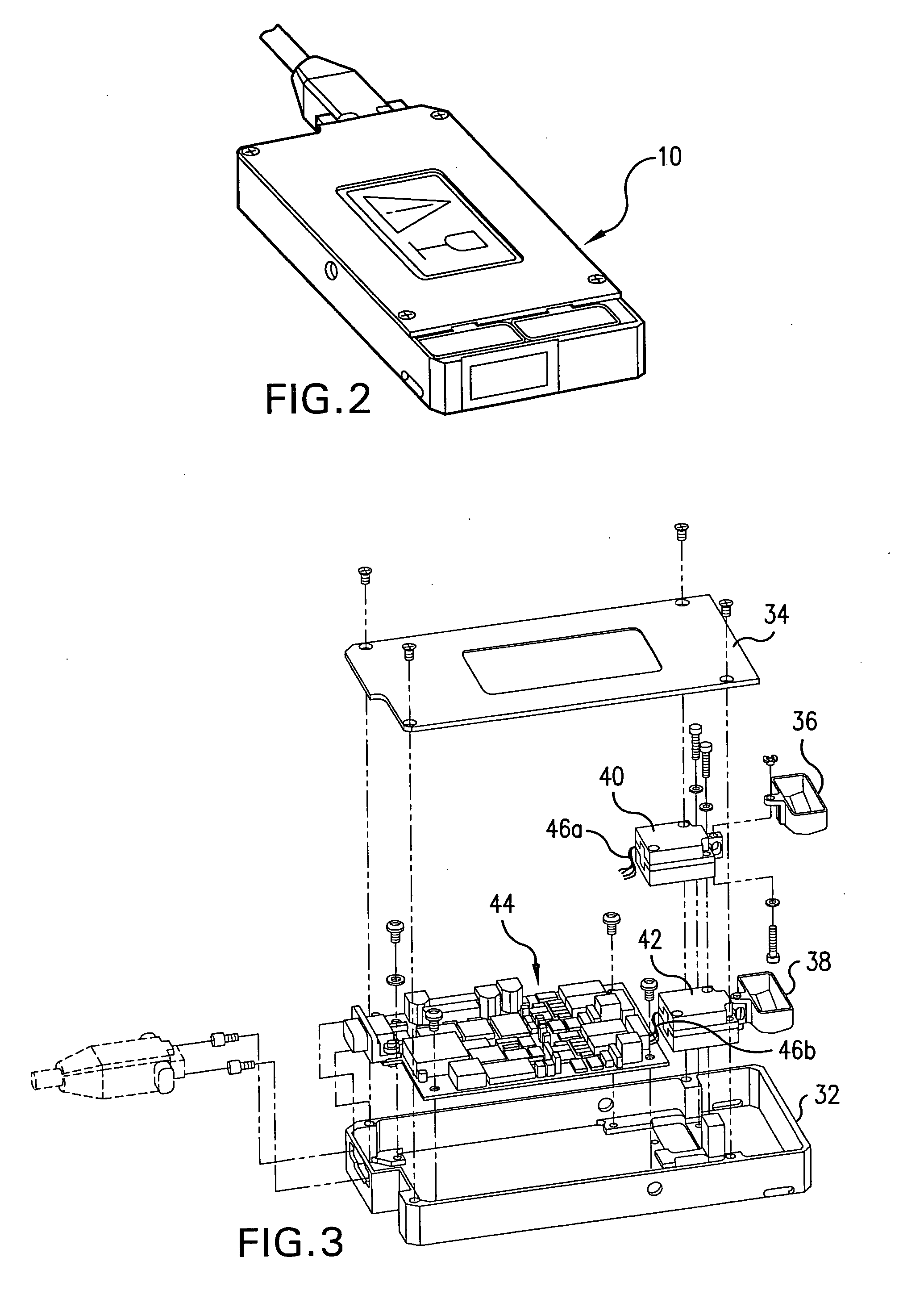
[0029] The apparatus and method of this invention enable a user to make accurate and precise measurements of the volumes of liquid dispensed in an analytical instrument by means of a portable measuring device, attachable to the analytical instrument. The portable measurement apparatus is effective over a range of operating temperatures and over a range of fluid densities. In addition, the apparatus of this invention makes it possible to verify the volume of liquid dispensed by a dispensing station within about 60 seconds. The apparatus of this invention can itself be calibrated in less than about 30 seconds. Furthermore, the apparatus of this invention allows the verification of a plurality of dispensing stations simultaneously.

Problems solved by technology

This measurement technique is subject to the effects of surface tension on the walls of the containment vessel.
The meniscus of the fluid dispensed does not always uniformly adhere to the walls of the containment vessel, thereby causing the volume verification tool to fail the requirements for making a reading of the measurement, and, consequently, delay the user in completing the system checks required to restore the “ABBOTT PRISM” system to normal operation.
Users often find the volume verification tool difficult to use, thereby resulting in delays.

Method used


Image

  • Apparatus and method for verifying the volume of liquid dispensed by a liquid-dispensing mechanism
  • Apparatus and method for verifying the volume of liquid dispensed by a liquid-dispensing mechanism
  • Apparatus and method for verifying the volume of liquid dispensed by a liquid-dispensing mechanism

Examples


examples

[0124]FIG. 22 is a schematic diagram of an embodiment of the digital electronics section of the electronic board of the apparatus of this invention. FIG. 23 is a schematic diagram of an embodiment of the A channel of the analog electronics section of the electronic board of the apparatus of this invention. FIG. 24 is a schematic diagram of an embodiment of the B channel of the analog electronics section of the electronic board of the apparatus of this invention. FIG. 25 is a schematic diagram of an embodiment of a balancing circuit for the A channel and the B channel of the apparatus of this invention. FIG. 25 also shows embodiments of a power filter and a power regulator. Table III lists the names of the parts shown in FIGS. 22, 23, 24, and 25.

TABLE IIIName of componentSymbol in FIGS. 22, 23, 24, 25Assigned terminalAAnalog deviceARAssigned terminalBCapacitorCElectrolytic capacitorELCAPDiode or rectifierCRLED signal deviceDSProbe point used by the test fixture ofEthe PCB assemblyC...


PUM

PropertyMeasurementUnit
massaaaaaaaaaa
sizeaaaaaaaaaa
distanceaaaaaaaaaa

Abstract

An apparatus for improving the procedure for quantifying the volume of liquid dispensed by a liquid-dispensing mechanism of an analytical instrument. The apparatus of this invention comprises (a) at least one weigh cup; (b) at least one standard mass; (c) at least one transducer assembly to convert a value of weight to an electrical response; and (d) at least one electronic circuit for converting the electrical response to a measurement of volume. This invention provides a method for calibrating readings of the volume of liquid dispensed by a liquid-dispensing mechanism of an analytical instruments so that absolute measurements of the volume of liquid dispensed can be obtained.

Description

[0001] This application is a division of U.S. application Ser. No. 10 / 409,282, filed Apr. 8, 2003.BACKGROUND OF THE INVENTION [0002] 1. Field of the Invention [0003] This invention relates to calibration of instruments for automated analysis of liquid samples. [0004] 2. Discussion of the Art [0005] Increasing public awareness of the need for the safety of the blood supply for transfusions has caused the transfusion industry to move toward the use of automated instruments, increased scrutiny by regulatory agencies, and centralization of blood bank testing. The “ABBOTT PRISM” system was conceived as an automated, high-volume, blood banking virology instrument that would reduce the need for highly trained instrument operators. According to the “ABBOTT PRISM” system, after the instrument automatically scans the samples during the loading process, the operator follows a simple set of menu-driven commands to initiate sample runs. The system can process 160 samples, or up to 960 tests, per...

Claims


Application Information

Patent Timeline
Patent Type & Authority Applications(United States)
IPC IPC(8): G01F25/00G01F13/00B01L99/00G01G17/04G01N35/00G01N35/10
CPCB01L3/0293B01L2200/148G01N2035/00217G01G17/04G01N35/1016G01F25/0092
Inventor KLOSTERMAN, KURT M.RAJAGOPAL, GANESHJIBSON, LARRY R.DEMPSKI, JAMES L.MATUSZEWSKI, PAUL A.STEWART, JEFFREY W.SWANSON, JEFFREY R.TIPOTSCH, DAVID M.YOUNGS, RANDALL E.ABUNIMEH, NOMAN A.
Owner ABBOTT LAB INC
Learn More