Electron beam irradiation device

a technology of irradiation device and electron beam, which is applied in the direction of x-ray tube target material, x-ray tube target and convertor, etc., and can solve problems such as late control

Active Publication Date: 2006-12-07
DAI NIPPON PRINTING CO LTD
View PDF3 Cites 9 Cited by
  • Summary
  • Abstract
  • Description
  • Claims
  • Application Information

AI Technical Summary

Benefits of technology

[0016] According to the electron beam irradiation device of this aspect, the oxygen concentration in the irradiation chamber can be monitored by utilizing the oxygen concentration detection device. As the oxygen concentration detection device is provided at the downstream of the filter, even in the environment in which the dust such as paper powder occur from the irradiated object come along with the irradiation of the electron beam, the filter can remove the dust and the oxygen concentration in the irradiation chamber can be detected precisely. Further, because the clogging of the filter can be judged from detected value of the pressure detection device and an alarm can be output, the maintenance of the filter is promoted to the operator, and the risk that the state which an error is generated in the detected value of the oxygen concentration by clogging of the filter is left can be removed.

Problems solved by technology

In this case, even if the rise of the oxygen concentration is detected and the valve travel of the flow regulating valve is increased, there is risk that the control will be late.

Method used


Image

  • Electron beam irradiation device
  • Electron beam irradiation device
  • Electron beam irradiation device

Examples


Embodiment Construction

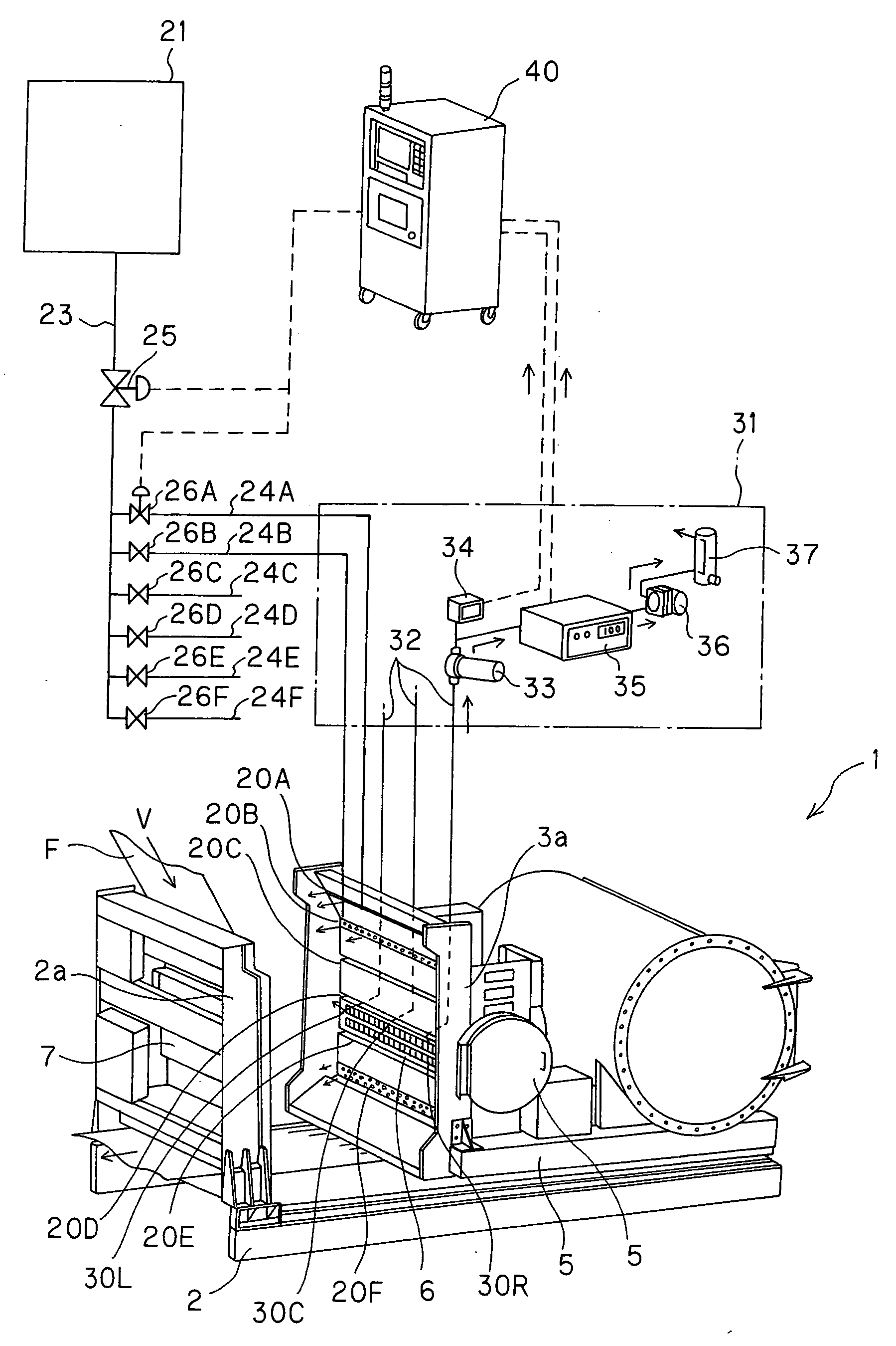
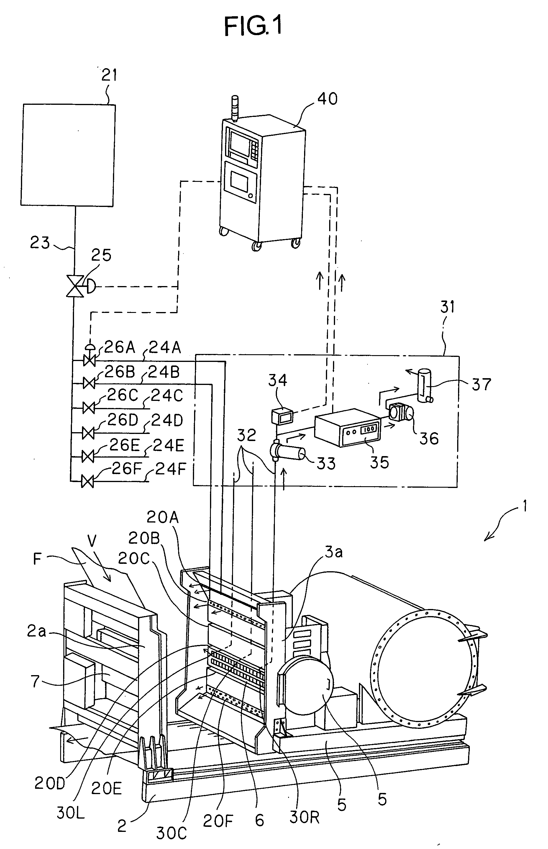
[0023]FIG. 1 is a view showing a main portion of an electron beam irradiation device according to one embodiment of the present invention. An electron beam irradiation device 1 comprises a fixed unit 2 installed on factory floors, and a movable unit 3 installed on the fixed unit 2. It is provided a rigid wall 2a at one end of the fixed unit 2, and it is provided a pair of rails 2b in front of the rigid wall 2a. The movable unit 3 is provided along the rails 2b movably, and a movable wall 3a facing to the rigid wall 2a is provided at one end thereof. The movable unit 3 advances toward the rigid wall 2a, and the movable wall 3a is made to be combined with the rigid wall 2a, then the irradiation chamber 4 of the electron beam is formed between both walls 2a, 3a (cf. FIG. 2). FIG. 1 shows the state that the movable unit 3 is moved back from the rigid wall 2a, and the irradiation chamber 4 is opened. It is provided an electron beam generator 5 to generate electron beam at the rear of the...


PUM

PropertyMeasurementUnit
oxygen concentration detectionaaaaaaaaaa
concentrationaaaaaaaaaa
flow rateaaaaaaaaaa

Abstract

To provide an electron beam irradiation device capable of reducing quantity of inert gas consumed while maintaining oxygen concentration in an irradiation chamber in appropriate level. An electron beam irradiation device to irradiate an electron beam to an irradiated object passing through an irradiation chamber while introducing inert gas into the irradiation chamber comprising an oxygen concentration detection device to detect oxygen concentration in the irradiation chamber; a main controlling valve to regulate flow rate of inert gas introduced in the irradiation chamber; a control unit to control valve travel of the main controlling valve so that the flow rate of the inert gas decreases when the oxygen concentration becomes low on the basis of the oxygen concentration detected by the oxygen concentration detection device.

Description

BACKGROUND OF THE INVENTION [0001] 1. Field of the Invention [0002] The present invention relates to an electron beam irradiation device to irradiate an electron beam to an irradiated object which passing an irradiation chamber while introducing inert gas in the irradiation chamber. [0003] 2. Description of the Related art [0004] There is known an electron beam irradiation device to irradiate an electron beam to a belt-shaped irradiated object such as a resin film and to conduct a processing such as bridging, hardening or reforming to the irradiated object. In this kind of irradiation device, when the electron beam is irradiated under the environment in which oxygen is exist, the inconvenience which the oxygen reacts to the electron beam and the irradiation energy of the electron beam is used sometimes occur. Therefore, as described in JP-B 63-8440, JP-A 5-60899 and JP-U 6-80200 for example, inert gas such as nitrogen is introduced in the irradiation chamber of the electron beam, an...

Claims


Application Information

Patent Timeline
Patent Type & Authority Applications(United States)
IPC IPC(8): C23C16/00
CPCG21K5/10H01J35/02H01J2235/082H01J2237/24571
Inventor NAKAO, SEITARO
Owner DAI NIPPON PRINTING CO LTD
Why Eureka
Try Eureka