Abrasive head attachment for nail polish removal tool

a nail polish and attachment head technology, applied in the field of grooming devices, can solve the problems of a good hour to completely clean a set of nails, a tedious task, and a large amount of nail polish removal, and achieve the effect of easy use, convenient use, and extended user's reach

Inactive Publication Date: 2006-12-07
MINERAL TECH
View PDF11 Cites 30 Cited by
  • Summary
  • Abstract
  • Description
  • Claims
  • Application Information

AI Technical Summary

Benefits of technology

[0012] Briefly, my attachment constitutes an abrasive member for a use on a nail polish removal tool having a main body leading to a narrow neck terminated by a small head having a working surface which may be rapidly moved by an electrically driven prime mover inside the body. The attachment or abrasive member is removably secured to the head so as to cover the working surface. When the tool is in use, the abrasive member or attachment is placed against the surface of a finger or toe nail with the result that the rubbing action of the abrasive member abrades away any polish or other covering on the nail. The surface of the abrasive member is such that the elements of that moving surface are able to penetrate into cracks and crevices enabling the tool to clean even around the cuticle.
[0013] Preferably, the tool is used with a polish removing agent or solvent. As we shall see, the solvent may be applied ...

Problems solved by technology

The removal of nail polish is a tedious task.
The procedure is also fairly messy because the nail polish becomes soft and finds it way into crevices in the cuticle.
This may take a good hour to completely clean a set of nails manually during which time one is exposed to the toxic fumes and annoying smell of the solvent.
However, these devices take up sp...

Method used


Image

  • Abrasive head attachment for nail polish removal tool
  • Abrasive head attachment for nail polish removal tool
  • Abrasive head attachment for nail polish removal tool

Examples


embodiment 120

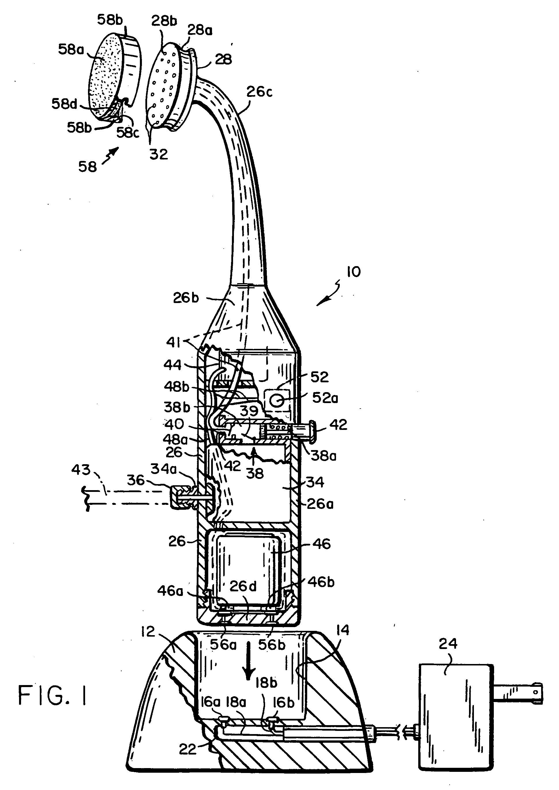
[0044] Refer now to FIGS. 5 and 6 which show another tool embodiment 120 comprising a housing 122 having a main body 122a and a smaller diameter elongated neck 122b leading to a head 122c. Like the tool depicted in FIG. 4, the head 122c is caused to vibrate. However, instead of placing the transducer or vibrator in the head as in FIG. 4, a known transducer 124 is located in the housing body 122a and extends into neck 122b so that when activated, the transducer causes the neck 122b as well as head 122c to vibrate. The transducer 124 is powered by a rechargeable battery 126 in main body 122a which is connected to the transducer by way of a finger-activated switch 128 mounted in the wall of housing 122.

[0045] Also, unlike the tool 76 in FIG. 4, the tool 120 is able to deliver a solvent to the working surface 130 of head 122c as the head is vibrated. More particularly, both neck 122b and head 122c are hollow. A tube 132 leads from the interior of the neck by way of a finger-operated val...

embodiment 170

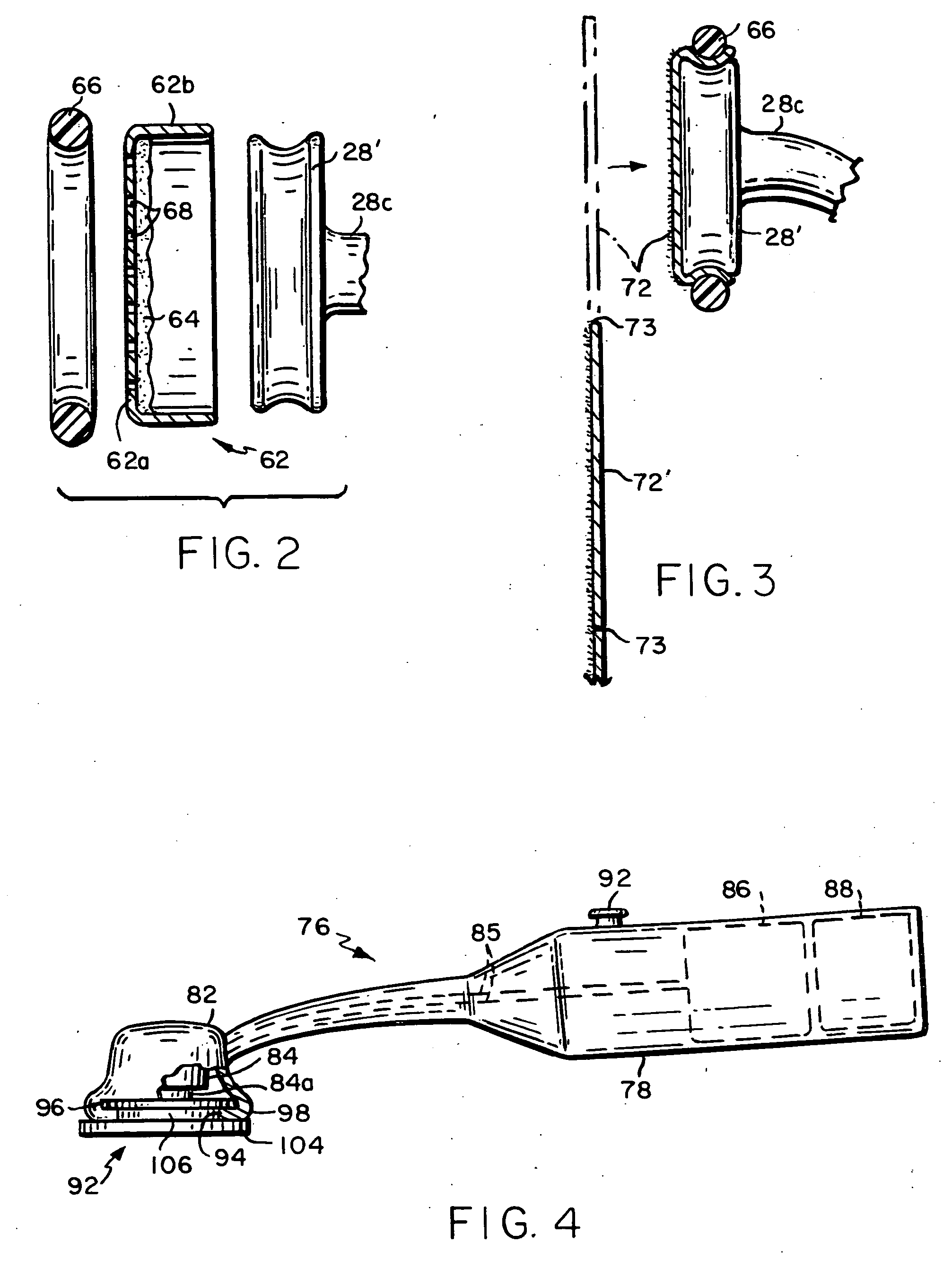
[0052] Refer now to FIG. 7 which illustrates a tool embodiment 170 whose head 172 has a working surface 174 which rotates instead of vibrates. Tool 170 has a main body 176a and a neck 176b leading to head 172. Body 176a contains an electric motor 178 as the prime mover powered by a rechargeable battery 179 and controlled by a switch 180 mounted in the wall of main body 176a and electrically connected between the two. The armature 178a of motor 178 is coupled to one end of a shaft 182 rotatably mounted in neck 176b. The opposite end of shaft 182 is located in head 172 and carries a bevel gear 184 which meshes with a second, orthogonal bevel gear 186 connected to a stub shaft 188 rotatably mounted in a bottom wall 172a of head 172. The stub shaft 188 extends through bottom wall 172a and connects to working surface 174 which is part of a relatively stiff, rotatable, perforated pad 175.

[0053] Tool 170 is used in conjunction with an abrasive member in the form of a swab shown generally a...


PUM


Abstract

A hand held nail polish removal tool includes a housing having a main body connected by an elongated neck to a head. An abrasive member is removably attached to the head and the tool contains a motor or transducer for causing the abrasive member to move so that when the abrasive member is positioned against a finger or toe nail, the abrasive member will abrade away any polish on the nail. The polish removal process may be accelerated by applying a solvent to the head attachment or member. This may be done by dipping that member in a solvent or by including a solvent in the member or by incorporating a solvent dispensing system in the housing which allows a solvent to be delivered via the head to the member's abrasive surface. Various different abrasive members for attachment to the head are disclosed.

Description

CROSS-REFERENCE TO RELATED APPLICATION [0001] This application is a continuation in part of Ser. No. 11 / 219,210, filed Sep. 2, 2005, which is a continuation-in-part of Ser. No. 10 / 243,877, filed Sep. 13, 2002, now U.S. Pat. No. 6,990,984.BACKGROUND OF THE INVENTION [0002] This invention relates to a grooming device. It relates more particularly to an abrasive head attachment for a hand held tool that removes nail polish from finger and toe nails. [0003] The removal of nail polish is a tedious task. The process usually involves wetting a pad or cotton swab with a volatile solvent and rubbing the coating repeatedly with the pad or swab until the polish is removed. The procedure is also fairly messy because the nail polish becomes soft and finds it way into crevices in the cuticle. Very often the solvent must be reapplied to the pad or swab and more than one swab must be used in order to remove the polish completely from the nail. This may take a good hour to completely clean a set of ...

Claims


Application Information

Patent Timeline
IPC IPC(8): A45D29/05A45D29/00
CPCA45D29/007A45D2001/045A45D29/14
Inventor O'DWYER, BARRY
Owner MINERAL TECH
Why Eureka
Try Eureka