Electronic package with direct cooling of active electronic components

a technology of electronic components and electronic packaging, applied in the field of electronic packaging, can solve the problems of reducing performance, reducing the service life of active electronic components on the die, and reducing the service life of active electronic components, so as to achieve the effect of convenient disassembly and assembly, and low cos

Inactive Publication Date: 2006-12-07
FORMFACTOR INC
View PDF51 Cites 24 Cited by
  • Summary
  • Abstract
  • Description
  • Claims
  • Application Information

AI Technical Summary

Benefits of technology

[0013] An advantage of the present invention is that embodiments of the present invention can include one or more dies which carry out high-power processing operations without reaching an overheating condition that degrades signal quality to an unacceptable level. A further advantage of a cooled high-density package embodiment according to the present invention is that it can compactly house a number of dies. In a compact embodiment, the size of the cavity within the package (also called the packaged component area) is only slightly larger than the footprint of the dies themselves.
[0014] One additional advantage of an electronic package with direct cooling according to the present invention is it is easy to disassemble for maintenance and repair. Another advantage of an electronic package with direct cooling according to the present invention is that it is inexpensive to assemble. Another advantage is that in certain embodiments electrical interconnects can be made to both the top and bottom of the package.
[0015] Further, in another embodiment, an electronic package according to the present invention includes a cooling member and a cooled package with one or more heat radiators such as cooling fins. The cooled package includes a housing that encloses a cavity. A coolant fills the cavity. One or more dies are mounted through compliant interconnects to a substrate within the cavity and are directly cooled by surrounding coolant. In this embodiment, however, heat is transferred away from the coolant by one or more heat radiators to the cooling member.
[0016] According to another embodiment, a method for direct cooling of active electronic components is provided. The method includes attaching active electronic components to a substrate with an active surface facing the substrate, sealing the attached active electronic components in a package, and circulating coolant through the package to directly contact the active surfaces of the active electronic components.
[0017] Further features and advantages of the present invention, as well as the structure and operation of various embodiments of the present invention, are described in detail below with reference to the accompanying drawings.BRIEF DESCRIPTION OF THE FIGURES

Problems solved by technology

An electronic package can house one or more dies, however, active electronic components on a die generate heat during operation.
Such heat needs to be removed from a package to avoid overheating and reduced performance.
This approach however is limited to back side cooling.
However, these LCMs only contact the exterior of an entire package.
In this case too, cooling the package exterior does not directly cool active surfaces of flip-chip bonded dies in a package.

Method used


Image

  • Electronic package with direct cooling of active electronic components
  • Electronic package with direct cooling of active electronic components
  • Electronic package with direct cooling of active electronic components

Examples


Embodiment Construction

Table of Contents

1. Overview and Discussion

2. Terminology

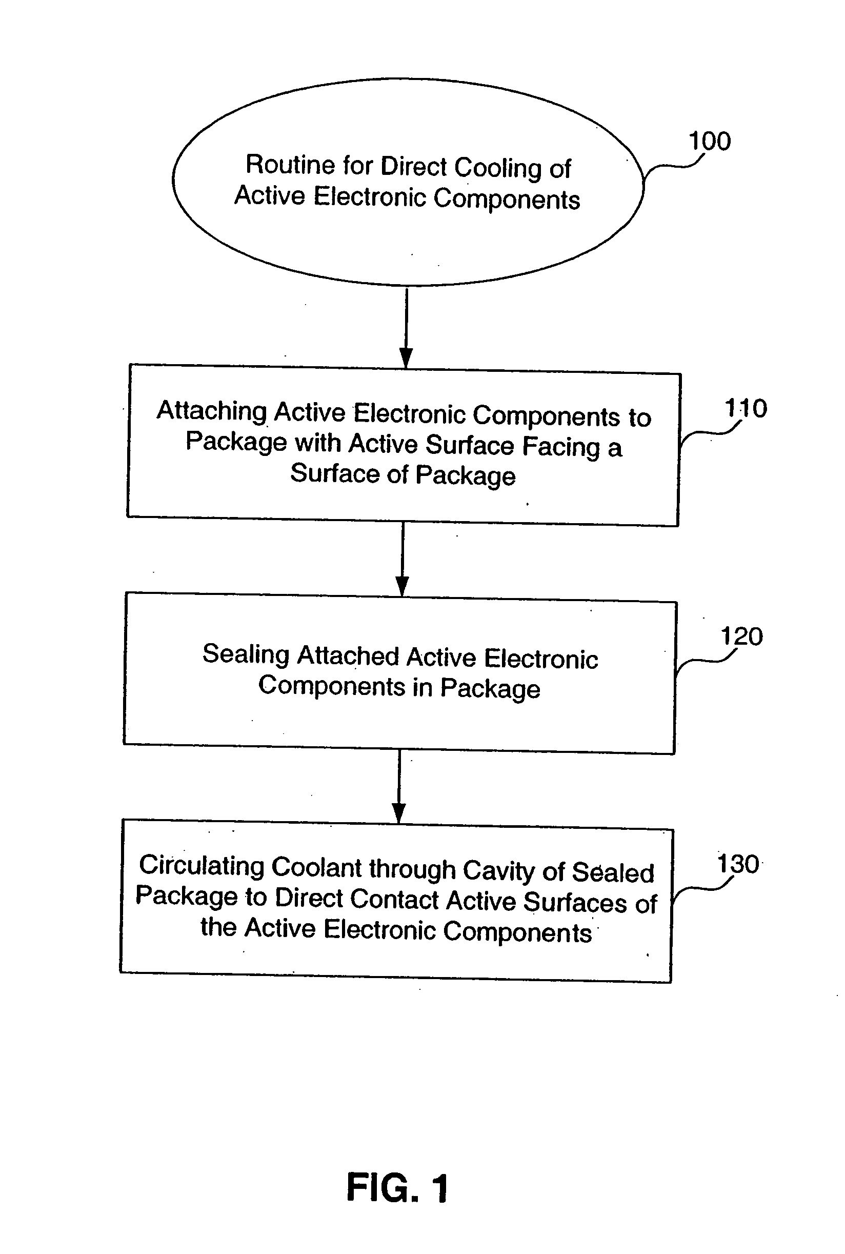
3. Routine for Direct Cooling of Active Electronic Components

4. Cooling Assembly

5. Cooled Package with One or More Dies

6. High-Density Cooled Packages

7. Cooled Package with Heat Radiator

8. Types of Spring Contacts

9. Conclusion

[0031] The following description is for the best modes presently contemplated for practicing the invention. This description is not to be taken in a limiting sense, but is made merely for the purpose of describing the general principles of the invention. The scope of the invention should be ascertained with reference to the claims. In the description of the invention that follows, like numerals or reference designators will be used to refer to like parts or elements throughout.

1. Overview and Discussion

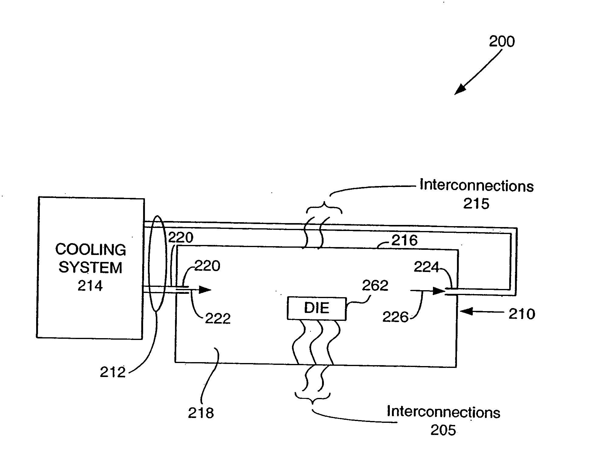
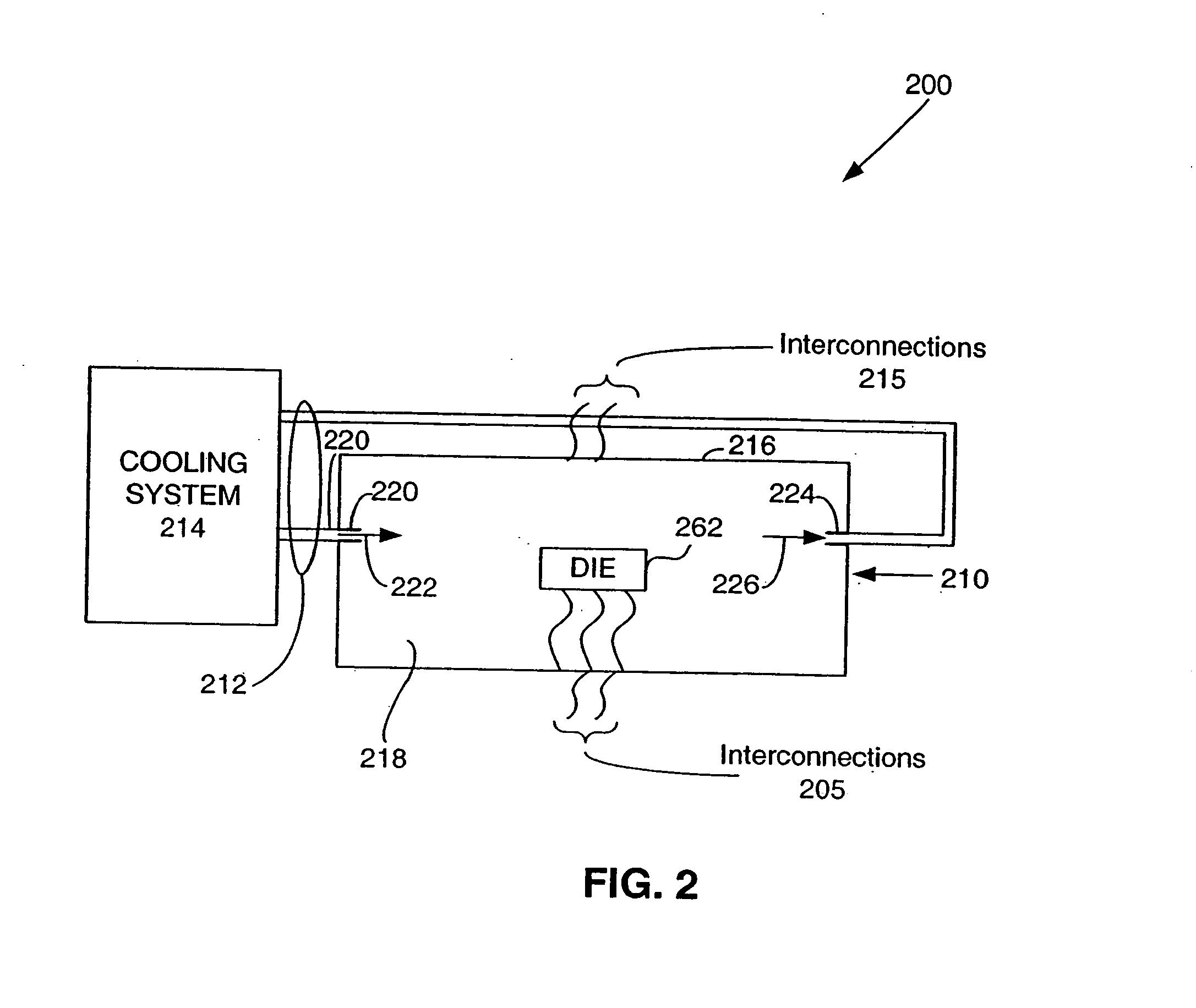
[0032] The present invention provides a cooling assembly. The cooling assembly includes a cooled package with one or more dies. Each die is directly cooled on one or more sides by a co...


PUM


Abstract

A cooling assembly includes a package with one or more dies cooled by direct cooling. The cooled package includes one or more dies with active electronic components. A coolant port allows a coolant to enter the package and directly cool the active electronic components of the dies.

Description

BACKGROUND OF THE INVENTION [0001] 1. Field of the Invention [0002] The present invention relates to electronic packaging. [0003] 2. Related Art [0004] An electronic package can house one or more dies, however, active electronic components on a die generate heat during operation. Such heat needs to be removed from a package to avoid overheating and reduced performance. The need for thermal management becomes greater as the number of dies desired to be housed in a single package increases and the operating load of each die increases. For example, thermal management is a significant concern for high-density packages which include multiple dies in a relatively small area. Further, dies are continually expected to include greater numbers of active electronic components such as transistors, and to operate at ever greater clock rates and input / output (IO) speeds. The need to dissipate heat is even more important in high-density packages with dies carrying out significant processing operat...

Claims


Application Information

Patent Timeline
Patent Type & Authority Applications(United States)
IPC IPC(8): H05K7/20G01R31/28
CPCG01R31/2863G01R31/2875H05K7/20236H01L2924/0002H01L2924/00
Inventor MILLER, CHARLES A.
Owner FORMFACTOR INC
Why Eureka
Try Eureka