
Wind turbine with friction drive power take off on outer rim

a technology of friction drive and wind turbine, which is applied in the direction of propellers, propulsive elements, water-acting propulsive elements, etc., can solve the problems of high cost of power transmission and energy production equipment, difficulty in producing electricity with the same frequency as the grid, and system cost more than those used in fixed-speed wind turbines

Inactive Publication Date: 2006-12-07
NEW WORLD GENERATION
View PDF5 Cites 59 Cited by
  • Summary
  • Abstract
  • Description
  • Claims
  • Application Information

AI Technical Summary

Benefits of technology

[0006] It is an object of the present invention to provide a wind turbine that can be controlled to operate energy producing equipment at variable speed rate of speed. It is further object of the present invention to provide a wind turbine without using a step up gearbox.

Problems solved by technology

This can result in heavy and costly power transmission and energy production equipment.
These systems are more costly than those used in fixed speed wind turbines.
With variable speed wind turbines, there is a difficulty of producing electricity with the same frequency as the grid because the wind velocity constantly changes and therefore the speed of rotation of the blades of the wind turbine varies.
With constant speed wind turbines, the frequency of the electricity produced can match the frequency of the grid, but difficulty arises in maintaining a constant speed with variable wind conditions.
Further, electrical energy cannot be produced by any wind turbine during periods when the wind is not blowing or is not blowing at a sufficient velocity to rotate the rotor of the wind turbine.

Method used


Image

  • Wind turbine with friction drive power take off on outer rim
  • Wind turbine with friction drive power take off on outer rim
  • Wind turbine with friction drive power take off on outer rim

Examples


Embodiment Construction

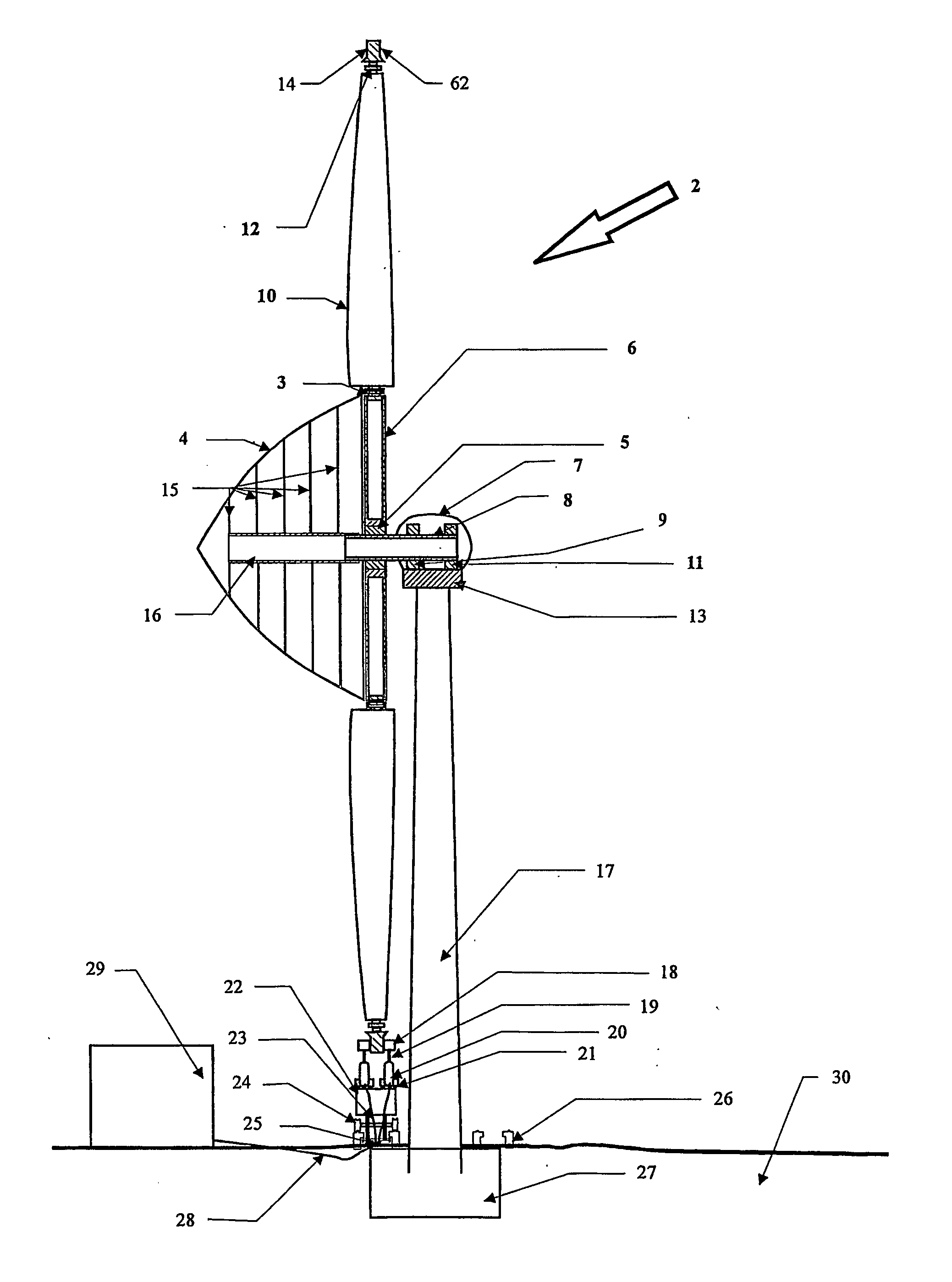
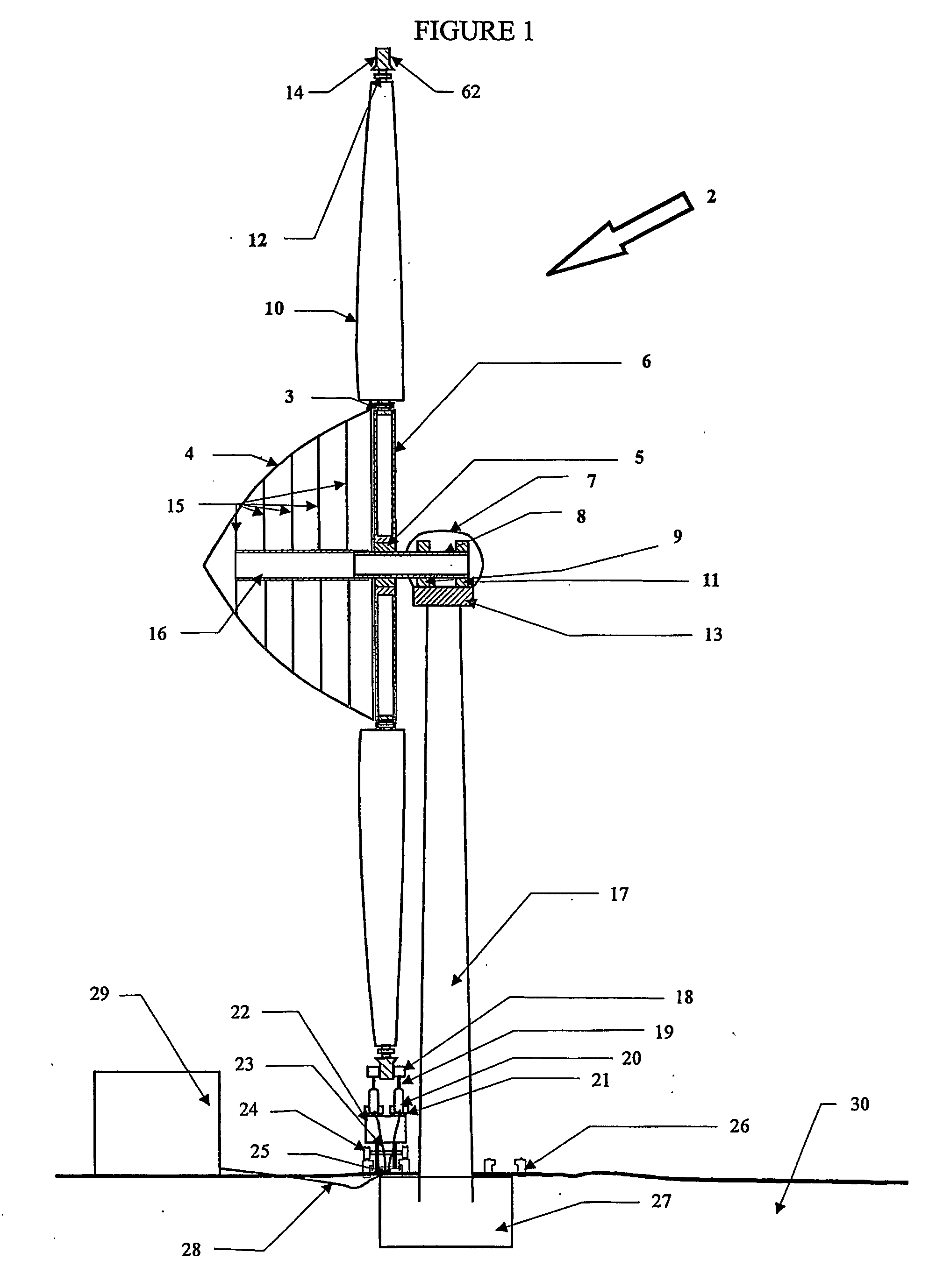
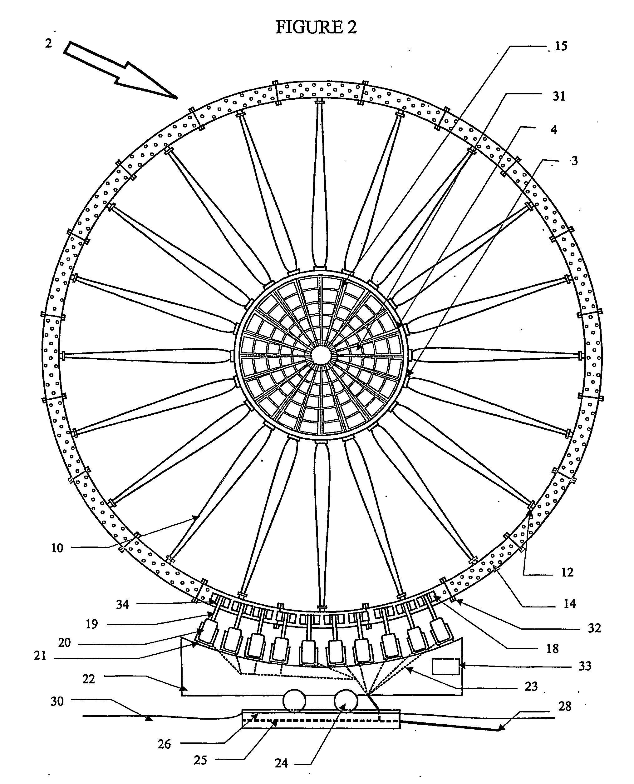
[0040] In FIGS. 1 and 2, a turbine 2 has a rotor with a hub 6 and a plurality of blades 10 extending outward from a root 3 to a tip 12. Preferably, the wind turbine has eight to twenty blades. Connected to and supported by each of the tips 12 is a ring with a front surface 14 and a back surface 62. Rotators 18 are located and mounted to be removably placed into contact with the front surface 14 and back surface 62 as the ring 1 rotates. The rotators each have a shaft 19 which is connected to energy producing equipment 20. The rotators are preferably tires mounted on a rim 34. The tires are preferably made of rubber. Steel or metal wheels can also be used as rotators. The energy producing equipment includes generators, compressors, pumps and the like. When the energy producing equipment is a generator, the rotation of the wind turbine 2 will cause the front surface 14 and back surface 62 of the ring to rotate. The tires will also rotate when they are in contact with the ring 1, there...


PUM


Abstract

A wind turbine has multiple blades (10) that are mounted on a shaft (19) with a ring around a circumference of the blades. There are tires (18) that are arranged to be in contact or out of contact with the ring. The tires draw generators when the tires are in contact with the ring and the ring is rotating. A controller monitors the wind conditions and controls the turbine to produce electricity or other-energy output or to shut down if the wind falls below a predetermined level.

Description

BACKGROUND OF THE INVENTION [0001] 1. Field of Invention [0002] This invention relates to a wind turbine and method of operation thereof for producing energy and, more particularly, to a wind turbine having multi-blades (for example eight to twenty), and a ring around the circumference thereof, the ring driving energy producing equipment. The blades are shaped with airfoils to produce maximum power coefficient. [0003] 2. Description of the Prior Art [0004] Wind turbines, including windmills, are known and are used to power energy production equipment including generators, compressors or pumps, as well as other devices. It is known to have the wind turbine connected to a shaft and the rotational energy in the shaft is then used to drive the energy producing equipment. Windmills or wind turbines have gearboxes to transfer the energy from the blades through the shaft to energy producing equipment. Some wind turbine manufactures are using a large diameter direct drive generator connecte...

Claims


Application Information

Patent Timeline
IPC IPC(8): B63H1/06F03D1/06F03D7/02F03D7/04F03D11/02F03D11/04
CPCF03D1/0608Y02E10/728F03D7/0224F03D7/0264F03D11/02F03D11/04F05B2240/2211F05B2260/402F05B2260/902F05B2270/1016F05B2270/3201F05B2270/321Y02E10/721Y02E10/723F03D7/0212F03D13/20F03D15/00Y02E10/72Y02E60/16Y02E70/30F03D9/17F03D9/25F03D9/28
Inventor MERSWOLKE, PAUL H.MEYER, CHARLES F.
Owner NEW WORLD GENERATION
Learn More