Integrated global layout and local microstructure topology optimization approach for spinal cage design and fabrication

a spinal cage and microstructure topology technology, applied in the direction of instruments, prostheses, joint implants, etc., can solve the problems of increasing the risk of bone resorption, increasing the largest pore size, and sacrifice the stiffness of the cage, so as to achieve sufficient mechanical strain and sufficient stability

Active Publication Date: 2006-12-07
RGT UNIV OF MICHIGAN
View PDF7 Cites 62 Cited by
  • Summary
  • Abstract
  • Description
  • Claims
  • Application Information

AI Technical Summary

Benefits of technology

[0010] In view of the drawbacks of the conventional approaches, a new design approach for providing a lumbar spine interbody fusion cage is disclosed. The new design approach uses topology optimization algorithms to define the structural layout and the inner microstructures of the cage. This approach addresses the conflicting design issues of providing sufficient stability while at the same time providing appropriate porosity to deliver biofactors like cells, genes, and proteins and impart sufficient mechanical strain to maintain developing tissue. The interior architecture provided by the designed microstructures also reserves channel spaces for substance delivery in potential cell-based therapies and drug delivery. The present design approach allows a design to be modified for different patient types and allows the use of solid free-form fabrication techniques to manufacture the as-designed cage from commonly used biomaterials including but not limited to titanium, hydroxyapatite, tricalcium phosphate, polylactic acid, polyglycolic acid, and Poly (propylene fumarate).

Problems solved by technology

Nonetheless, the rigid shells may shield an implanted graft or ingrown bone tissue from sufficient mechanical stimulus, (known as “stress-shielding”) thus increasing the risk for decreased mineralization and bone resorption and provide a stress-shielded environment inside the device.
The decreasing bone mineral density is believed to be attributable to the lack of mechanical stimuli which increases the risk of bone resorption.
However, it is important to note that increasing the largest pore size sacrifices the stiffness of the cage.
This may yield excess compliance causing unexpected deformation and instability.
Conventional designs do not have the flexibility to meet the multiple design requirements necessary to achieve sufficient rigidity, reduced stress shielding, and large porosity for biofactor delivery.
However, the material substitutes bring up additional issues of biocompatibility and immune response.
In addition, there may be a limited supply of cortical bone allograft.

Method used


Image

  • Integrated global layout and local microstructure topology optimization approach for spinal cage design and fabrication
  • Integrated global layout and local microstructure topology optimization approach for spinal cage design and fabrication
  • Integrated global layout and local microstructure topology optimization approach for spinal cage design and fabrication

Examples


Embodiment Construction

[0023] The following description of the preferred embodiments is merely exemplary in nature and is in no way intended to limit the invention, its application, or uses.

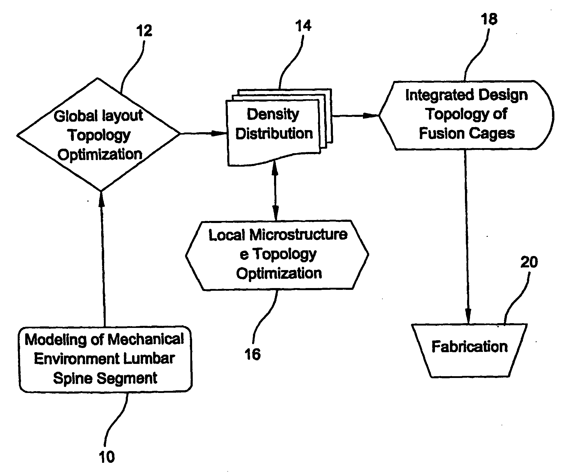
[0024] In accordance with the teachings of the present invention, a method of designing an interbody fusion cage is provided. The cage is designed to provide mechanical support, and scaffolding for tissue ingrowth and biofactor delivery to facilitate arthrodesis (spine fusion). The new design approach balances the conflicting requirements of providing stability for support, compliance to avoid stress shielding, and porosity for biofactor delivery.

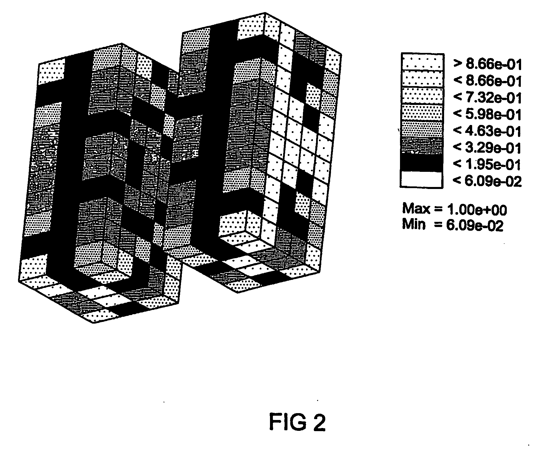
[0025] As one skilled in the art may appreciate, stability requires a dense material while compliance and biofactor delivery require great porosity. The present invention employs an optimization approach to achieve a balanced design. Specifically, a material layout is created such that stability, compliance and porosity requirements are optimally balanced. Even more particul...


PUM

PropertyMeasurementUnit
porosityaaaaaaaaaa
porosityaaaaaaaaaa
displacementsaaaaaaaaaa

Abstract

A method of designing an interbody fusion cage is disclosed. The method uses topology optimization algorithms to define the structural layout and the inner microstructures of the cage. After the structural layout is defined, a density distribution process is performed. Based on the density distribution, the inner microstructures of the cage are defined.

Description

GOVERNMENT SUPPORT [0001] This invention was made with government support under grant numbers DE13416 and DE13608 awarded by the National Institutes of Health. The government has certain rights in the invention.FIELD OF THE INVENTION [0002] The present invention relates to a method of designing microstructure topology and more particularly, to a method of designing optimized microstructure topology for spinal cage design and fabrication. BACKGROUND OF THE INVENTION [0003] Conventional designs of spinal interbody fusion cages have mainly focused on providing immediate strength to maintain disc height and shielding bone grafts within the cage. As such, the geometric features of conventional designs show little distinction from each other and most designs fall into a category consisting of pipe shapes with thick shells as outer walls and a hollow interior space that brackets the fill of grafting materials. [0004] For example, the following interbody fusion devices were tested in a stud...

Claims


Application Information

Patent Timeline
Patent Type & Authority Applications(United States)
IPC IPC(8): G06F19/00A61BA61F2/00A61F2/02A61F2/28A61F2/30A61F2/44
CPCA61F2/30942A61F2310/00023A61F2002/2817A61F2002/30006A61F2002/30011A61F2002/30062A61F2002/30153A61F2002/30154A61F2002/30261A61F2002/30263A61F2002/30303A61F2002/30678A61F2002/30785A61F2002/30838A61F2002/30943A61F2002/30955A61F2002/30958A61F2002/30962A61F2002/30971A61F2210/0004A61F2230/0019A61F2230/0021A61F2230/0063A61F2230/0082A61F2230/0084A61F2250/0015A61F2250/0018A61F2250/0023A61F2/4455B33Y80/00B33Y50/00A61F2002/30677A61F2002/30957
Inventor LIN, CHIA YINGHOLLISTER, SCOTT J.LIN, CHENG-YU
Owner RGT UNIV OF MICHIGAN
Why Eureka
Try Eureka