Methods and systems for generation of gases

a technology of gas generation and system, applied in the field of pressure-swinging adsorption (psa) nitrogen generator, can solve problems such as problems for many applications

Inactive Publication Date: 2006-12-14
INNOVENTOR ENG
View PDF28 Cites 10 Cited by
  • Summary
  • Abstract
  • Description
  • Claims
  • Application Information

AI Technical Summary

Problems solved by technology

However, the presence of CO2 ca...

Method used


Image

  • Methods and systems for generation of gases
  • Methods and systems for generation of gases
  • Methods and systems for generation of gases

Examples


Embodiment Construction

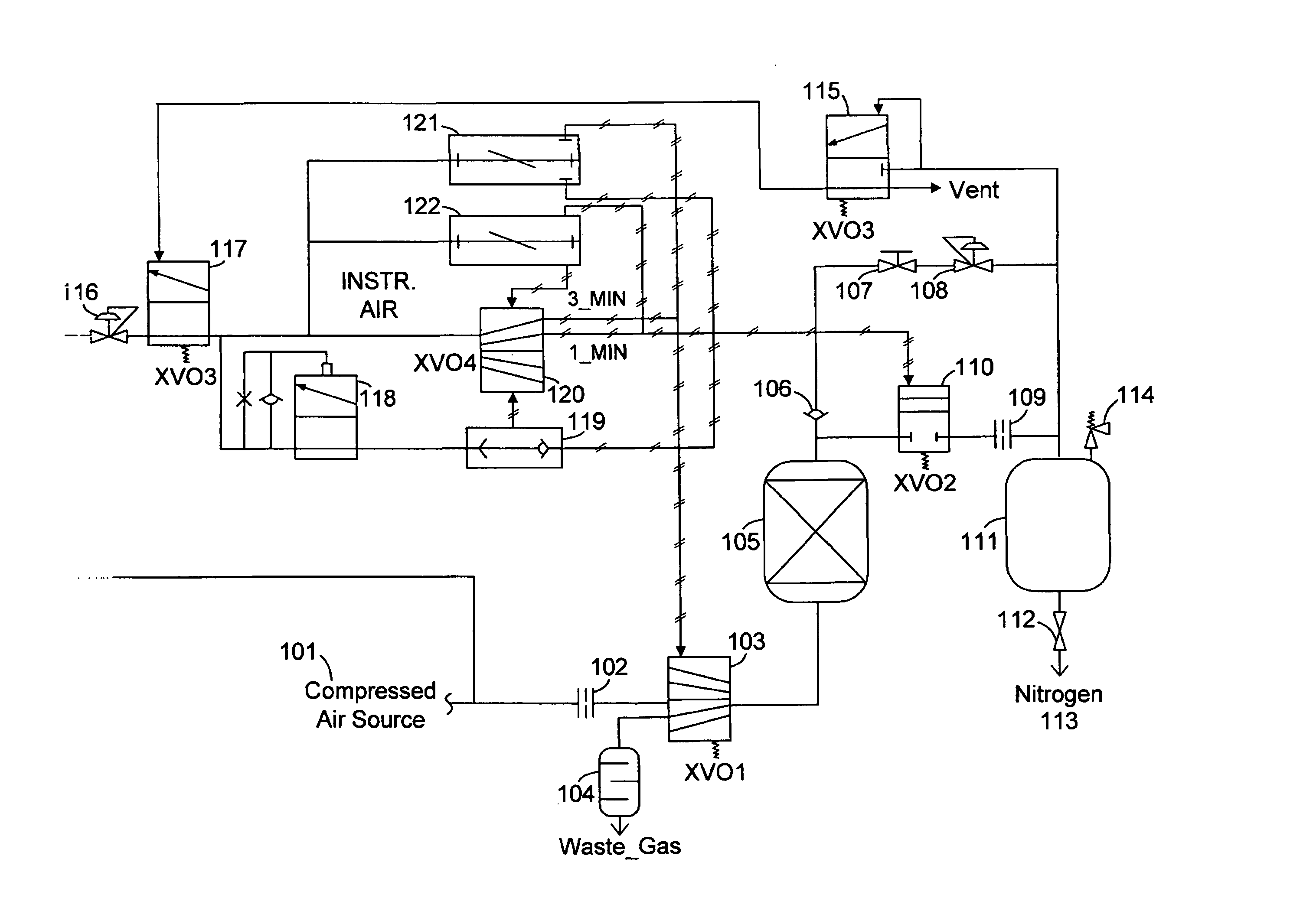
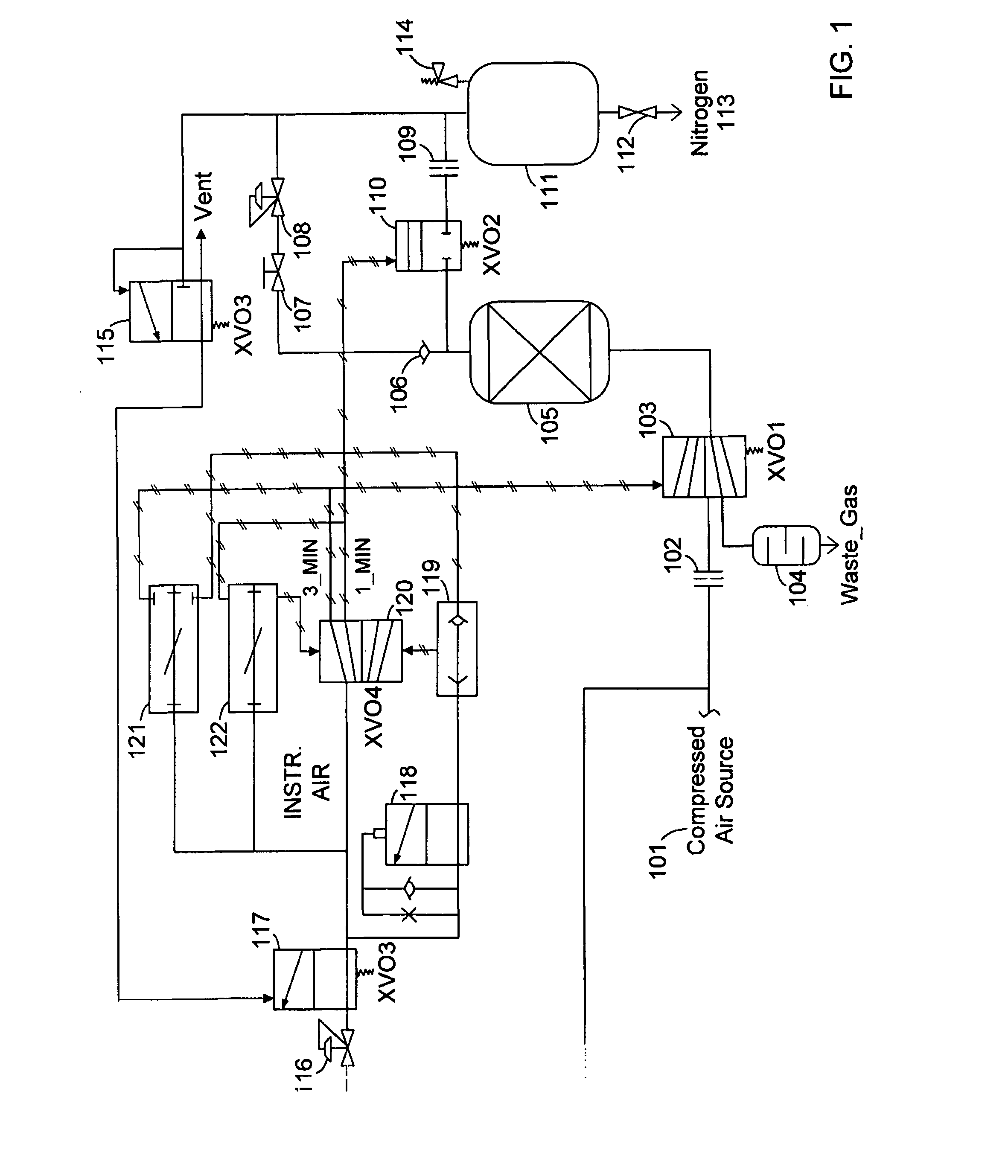
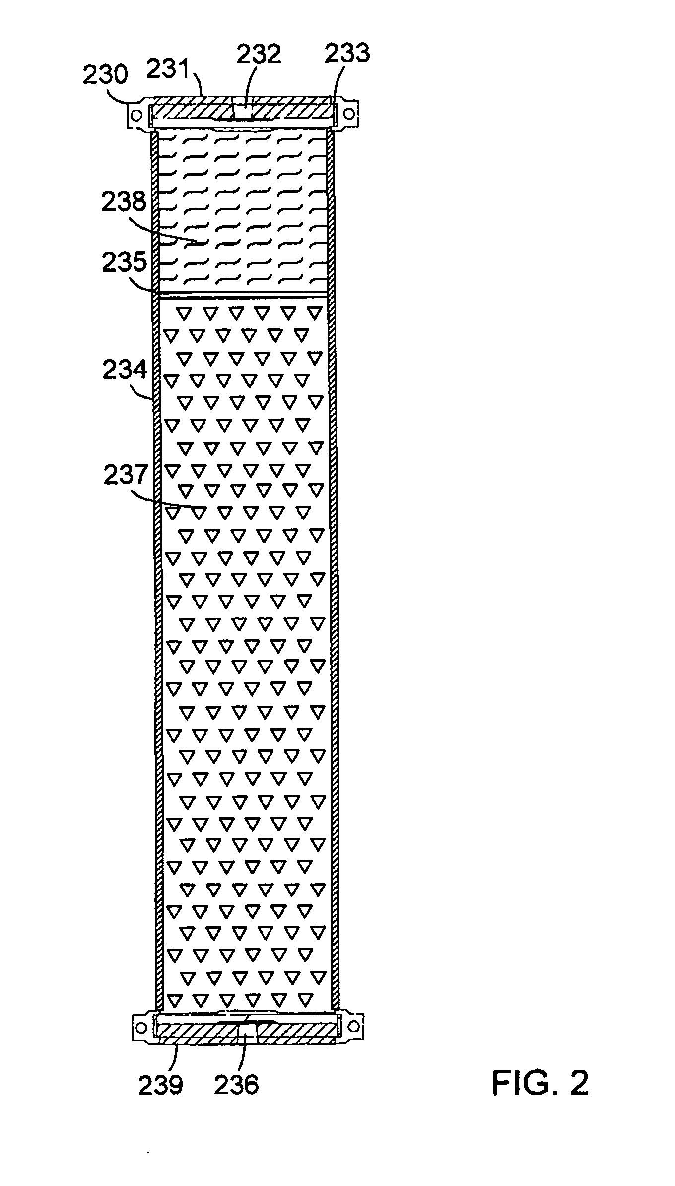
[0012] Described herein are methods and apparatus that reduce cost and complexity, and improve performance, of pressure swing adsorbtion (PSA) nitrogen generators. The ability to control timing of a control system is provided with a pneumatic system that obviates the need for a programmable logic controller (PLC) or electromechanical timer, and allows operation of the system without requiring electricity. Variants of the system described herein are used for dual bed PSA systems. However the primary application is for single bed (monobed) PSA systems. Also provided is a method of constructing vessels designed for easy maintenance and low cost as is a method of obtaining quality flow distribution of gas in a space-efficient and cost-effective manner.

[0013]FIG. 1 is a block diagram of a time control system 100. As shown in FIG. 1, compressed air, 101, is supplied to system 100. A small amount of compressed air diverts to a pressure regulator 117, which reduces pressure downstream of 1...


PUM

PropertyMeasurementUnit
Pressureaaaaaaaaaa
Ratioaaaaaaaaaa

Abstract

A method of operating a nitrogen generator is provided, wherein the method includes providing a source of compressed air and operating a plurality of pneumatic valves with the compressed air. The method also includes operating at least one pneumatic timer to toggle the nitrogen generator between a production mode where compressed air is channeled to a nitrogen adsorber to produce nitrogen, and a regeneration mode where substantially oxygen-rich air in the nitrogen adsorber is exhausted into the atmosphere.

Description

CROSS REFERENCE TO RELATED APPLICATIONS [0001] This application claims the benefit of U.S. provisional application No. 60 / 684,510 filed May 25, 2005, which is herein incorporated by reference in its entirety.BACKGROUND OF THE INVENTION [0002] This invention relates generally to generators, and more specifically to pressure-swing-adsorption (PSA) nitrogen generators. Herein, the generators are generally referred to as nitrogen generators. However the disclosed embodiments also apply to generators of other gases, such as oxygen, methane, etc. [0003] Nitrogen is used for many applications. The most common general application is taking advantage of its inert property, typically to keep oxygen away from combustible products or products that degrade with exposure to oxygen and / or moisture. Systems are known that utilize combusted fossil fuel to produce a mixture consisting of approximately 88% N2 and 12% CO2 for use as an inert gas. However, the presence of CO2 caused a problem for many a...

Claims


Application Information

Patent Timeline
IPC IPC(8): B01D53/02
CPCB01D53/047Y02C20/20B01D2253/104B01D2253/116B01D2253/25B01D2256/10B01D2257/102B01D2257/104B01D2257/80B01D2259/40003B01D2259/40007B01D2259/40052B01D2259/401B01D2259/4145B01D53/261
Inventor HOLT, THORSTEINWINKLER, GARY
Owner INNOVENTOR ENG
Why Eureka
Try Eureka