Linear vacuum deposition system

a vacuum deposition and vacuum technology, applied in the direction of conveyor parts, woodworking apparatus, turning machine accessories, etc., can solve the problems of increasing the cost of current production equipment, requiring a relatively large floor space, and requiring a large amount of equipment to achieve the effect of increasing throughput, and increasing the incremental cost of adding additional equipment to the production lin

Inactive Publication Date: 2006-12-14
APPLIED MATERIALS INC
View PDF11 Cites 28 Cited by
  • Summary
  • Abstract
  • Description
  • Claims
  • Application Information

AI Technical Summary

Benefits of technology

[0010] Embodiments of a vacuum conveyor system are provided herein. In one embodiment a vacuum conveyor system includes a first vacuum sleeve and a plurality of rollers that support and move substrates through the first vacuum sleeve. The first vacuum sleeve has a port for sealably coupling the first vacuum sleeve to a process chamber. A first substrate handler is disposed proximate the connector port. Multiple ports may be provided for sealably coupling the first vacuum sleeve to a plurality of process chambers. A dedicated substrate handler is provided for each process chamber. A second vacuum sleeve may be sealably coupled to an opposing side of the process chambers. The vacuum conveyor system may be modular with independent modules linked via load lock chambers. The plurality of rollers may compensate for any sag of the leading edge of a substrate being transported thereupon.

Problems solved by technology

However, the current production equipment is getting more costly.
For example, cluster tools suitable for vacuum processing of large glass substrates, e.g., 1 m2 and larger, require a relatively large floor space and are very costly.
As such, the incremental cost of adding additional equipment to the production line to increase throughput is very expensive.

Method used


Image

  • Linear vacuum deposition system
  • Linear vacuum deposition system
  • Linear vacuum deposition system

Examples


Embodiment Construction

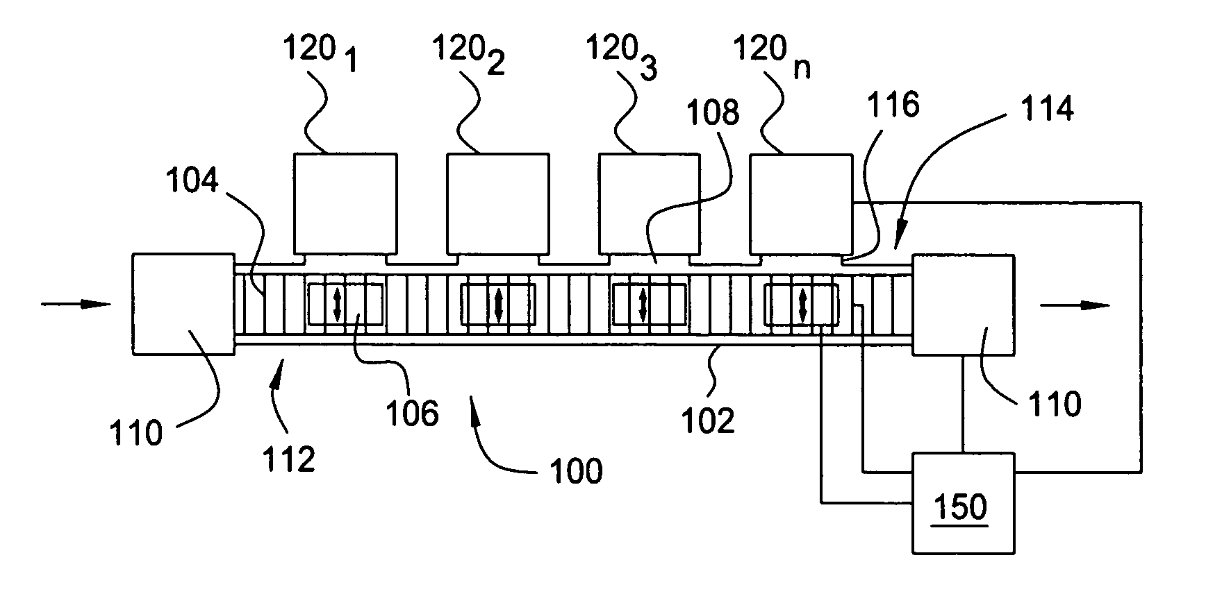
[0029] Embodiments of a vacuum conveyor system are provided herein. The vacuum conveyor system a sealed, sub-atmospheric pressure substrate transport system that may be coupled to a plurality of process chambers to facilitate transfer of substrates between process chambers while remaining at processing pressures, i.e., in a vacuum. The vacuum conveyor system may be connected to any load locks or process chambers, including conventional load locks and process chambers. The process chambers may be any process chambers that operate at a vacuum, such as chemical vapor deposition (CVD) chambers, physical vapor deposition (PVD) chambers, atomic layer deposition (ALD) chambers, or any other deposition or other processing chamber that operates at sub-atmospheric pressures.

[0030]FIG. 1A depicts a simplified top view of a vacuum conveyor system 100. The vacuum conveyor system 100 comprises a vacuum sleeve 102 having one or more ports 108 and enclosing a plurality of rollers 104 and one or mo...


PUM

PropertyMeasurementUnit
heightaaaaaaaaaa
heightaaaaaaaaaa
helix angleaaaaaaaaaa

Abstract

Embodiments of a vacuum conveyor system are provided herein. In one embodiment a vacuum conveyor system includes a first vacuum sleeve having a plurality of rollers that support and move substrates through the first vacuum sleeve. A port is provided for sealably coupling the first vacuum sleeve to a process chamber. A first substrate handler is disposed proximate the port. Multiple ports may be provided for sealably coupling the first vacuum sleeve to a plurality of process chambers. A dedicated substrate handler is provided for each process chamber. A second vacuum sleeve may be sealably coupled to an opposing side of the process chambers. The vacuum conveyor system may be modular with independent modules linked via load lock chambers. The plurality of rollers may compensate for any sag of the leading edge of a substrate being transported thereupon.

Description

CROSS-REFERENCE TO RELATED APPLICATION [0001] This application claims benefit of U.S. Provisional Application Ser. No. 60 / 689,621, entitled “Linear Vacuum Deposition System”, filed Jun. 10, 2005, which is hereby incorporated by reference in its entirety. This application is additionally related to U.S. application Ser. No. (Unknown), entitled “Substrate Handling System”, filed herewith by Wendell Blonigan, et al., and U.S. application Ser. No. (Unknown), entitled “Substrate Conveyor System”, filed herewith by Wendell Blonigan, et al., both of which are hereby incorporated by reference in its entirety.BACKGROUND OF THE INVENTION [0002] 1. Field of the Invention [0003] Embodiments of the present invention generally relate to a vacuum deposition system. More specifically, the present invention relates to a vacuum conveyor system for transporting substrates within a vacuum environment. [0004] 2. Description of the Related Art [0005] Glass substrates are being used to fabricate active ma...

Claims


Application Information

Patent Timeline
Patent Type & Authority Applications(United States)
IPC IPC(8): B23Q7/00
CPCC23C14/56H01L21/67739C23C16/54C23C14/568
Inventor WHITE, JOHN M.BLONIGAN, WENDELL T.
Owner APPLIED MATERIALS INC
Why Eureka
Try Eureka