System for studying power of laser beam

Inactive Publication Date: 2006-12-14
SAMSUNG ELECTRONICS CO LTD
View PDF5 Cites 2 Cited by
  • Summary
  • Abstract
  • Description
  • Claims
  • Application Information

AI Technical Summary

Benefits of technology

[0012] Therefore, an aspect of the invention is to provide a laser beam power studying system wherein a same amplifier is used in a recording laser beam power studying operation and a reproduction laser beam power studying operation, thus raising reliability of the laser beam power studying results and simplifying the circuit configuration of the system.

Problems solved by technology

However, such a conventional laser beam power studying system is disadvantageous in that, because the different amplifiers are used in the recording laser beam power studying operation and the reproduction laser beam power studying operation, the accurate setting of references for laser beam power control may be difficult due to gain and offset differences between the amplifiers.
In addition, the recording laser beam power studying path and the reproduction laser beam power studying path must be controlled separately from each other, thereby increasing load on the microcomputer.
Moreover, the use of inaccurate references for laser beam power control may cause the laser beam power control to be performed inaccurately or for a longer time.

Method used


Image

  • System for studying power of laser beam
  • System for studying power of laser beam
  • System for studying power of laser beam

Examples


Embodiment Construction

[0023] Reference will now be made in detail to the embodiments of the present invention, examples of which are illustrated in the accompanying drawings, wherein like reference numerals refer to the like elements throughout. The embodiments are described below to explain the present invention by referring to the figures.

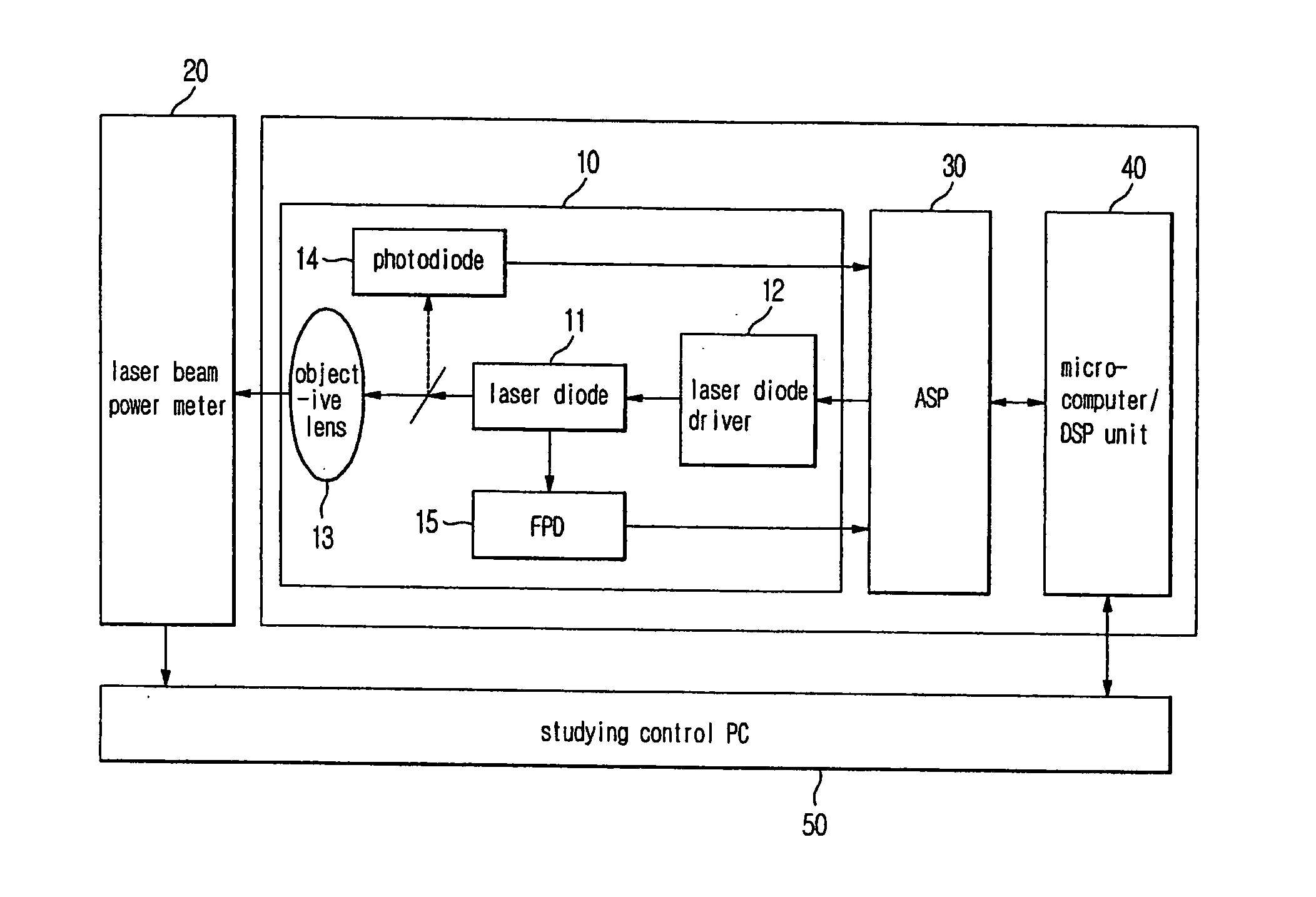
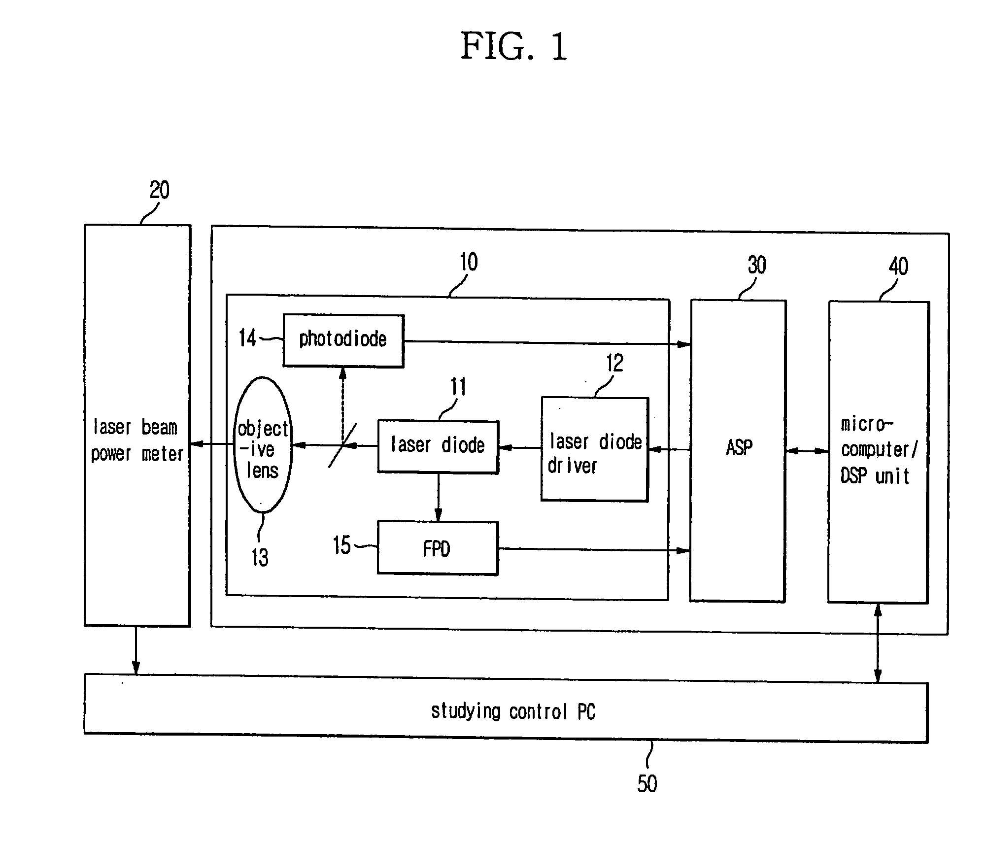
[0024]FIG. 1 shows a configuration of a laser beam power studying system according to an exemplary embodiment of the present invention. As shown in FIG. 1, the laser beam power studying system comprises a pickup 10, a laser beam power meter 20, an analog signal processor (ASP) 30, a microcomputer / digital signal processor (DSP) unit 40, and a studying control personal computer (PC) 50.

[0025] The pickup 10 includes a laser diode 11 emitting a laser beam, a laser diode driver 12 driving the laser diode 11, an objective lens 13 focusing the laser beam from the laser diode 11 on an optical disc to form a spot thereon, a photodiode 14 receiving a laser beam reflected from...


PUM


Abstract

A laser beam power studying system for studying laser power in a reproducing mode and a recording mode of an optical recording apparatus. A laser beam having different powers in the recording mode and the reproduction mode is emitted and a first part of the laser beam is measured. A second part of the laser beam is measured by a front photo diode and a signal corresponding to the measurement by the front photo diode is amplified by a single amplifier in both reproducing recording study operations. Relational expression between measurements of the first part of the laser beam and the second part of the laser beam at different power levels of the laser beam is developed for both the recording and reproducing modes.

Description

CROSS-REFERENCE TO RELATED APPLICATIONS [0001] This application claims the benefit of Korean Patent Application No. 2005-44365, filed on May 26, 2005 in the Korean Intellectual Property Office, the disclosure of which is incorporated herein by reference. BACKGROUND OF THE INVENTION [0002] 1. Field of the Invention [0003] The present invention relates to a system for studying power of a laser beam, and, more particularly, to a laser beam power studying system for presetting references for control of power of a laser beam in a manufacturing process of an optical recording / reproduction apparatus. [0004] 2. Description of the Related Art [0005] In general, an optical recording / reproduction apparatus includes a recording automatic power control (APC) circuit controlling power of a laser beam in a recording operation, and a reproduction APC circuit controlling power of a laser beam in a reproduction operation, and is adapted to maintain the power of the laser beam at a predetermined value...

Claims


Application Information

Patent Timeline
IPC IPC(8): G01D18/00G11B7/125
CPCG11B7/1263G11B7/126
Inventor PARK, SANG YEAL
Owner SAMSUNG ELECTRONICS CO LTD
Why Eureka
Try Eureka