Eureka AIR delivers breakthrough ideas for toughest innovation challenges, trusted by R&D personnel around the world.

Optimized activation prevention assembly for a gas delivery system and methods therefor

Active Publication Date: 2006-12-14
LAM RES CORP
View PDF29 Cites 9 Cited by
  • Summary
  • Abstract
  • Description
  • Claims
  • Application Information

AI Technical Summary

Benefits of technology

[0044] Advantages of the invention include the avoidance of cost related to non-optimized gas delivery systems, in which all the plasma gases must generally be turned off and then vented, should an employee wish to physically access the gas distribution system for maintenance, assembly, or integration. Additional advantages include allowing gas stick component density to be maintained, while substantially improving employee safety by allowing each gas stick to be individually and quickly locked and / or tagged.

Problems solved by technology

That is, selectivity to a particular material tends to be very poor, since the direction of the ion bombardment is mostly perpendicular to the substrate surface in plasma etch process.
In addition, the etch rate of the pure ion etching is commonly low, depending generally on the flux and energy of the ion bombardment.
However, because plasma processing system operation may also be dangerous (i.e., poisonous gases, high voltages, etc.), worker safety regulations often mandate that plasma processing manufacturing equipment include activation prevention capability, such as a lockout / tagout mechanism.
In addition, although as previously stated, it is often mandated that plasma processing systems have lockout / tagout functionality, it is not generally common to integrate lockout / tagout functionality into inlet valve 302 because of space limitations within the gas distribution system.
However, the density of flow components to each other in a gas distribution system also tends to make individual gas stick activation prevention problematic, particularly at a gas stick inlet valve.

Method used


Image

  • Optimized activation prevention assembly for a gas delivery system and methods therefor
  • Optimized activation prevention assembly for a gas delivery system and methods therefor
  • Optimized activation prevention assembly for a gas delivery system and methods therefor

Examples


Embodiment Construction

[0032] The present invention will now be described in detail with reference to a few preferred embodiments thereof as illustrated in the accompanying drawings. In the following description, numerous specific details are set forth in order to provide a thorough understanding of the present invention. It will be apparent, however, to one skilled in the art, that the present invention may be practiced without some or all of these specific details. In other instances, well known process steps and / or structures have not been described in detail in order to not unnecessarily obscure the present invention.

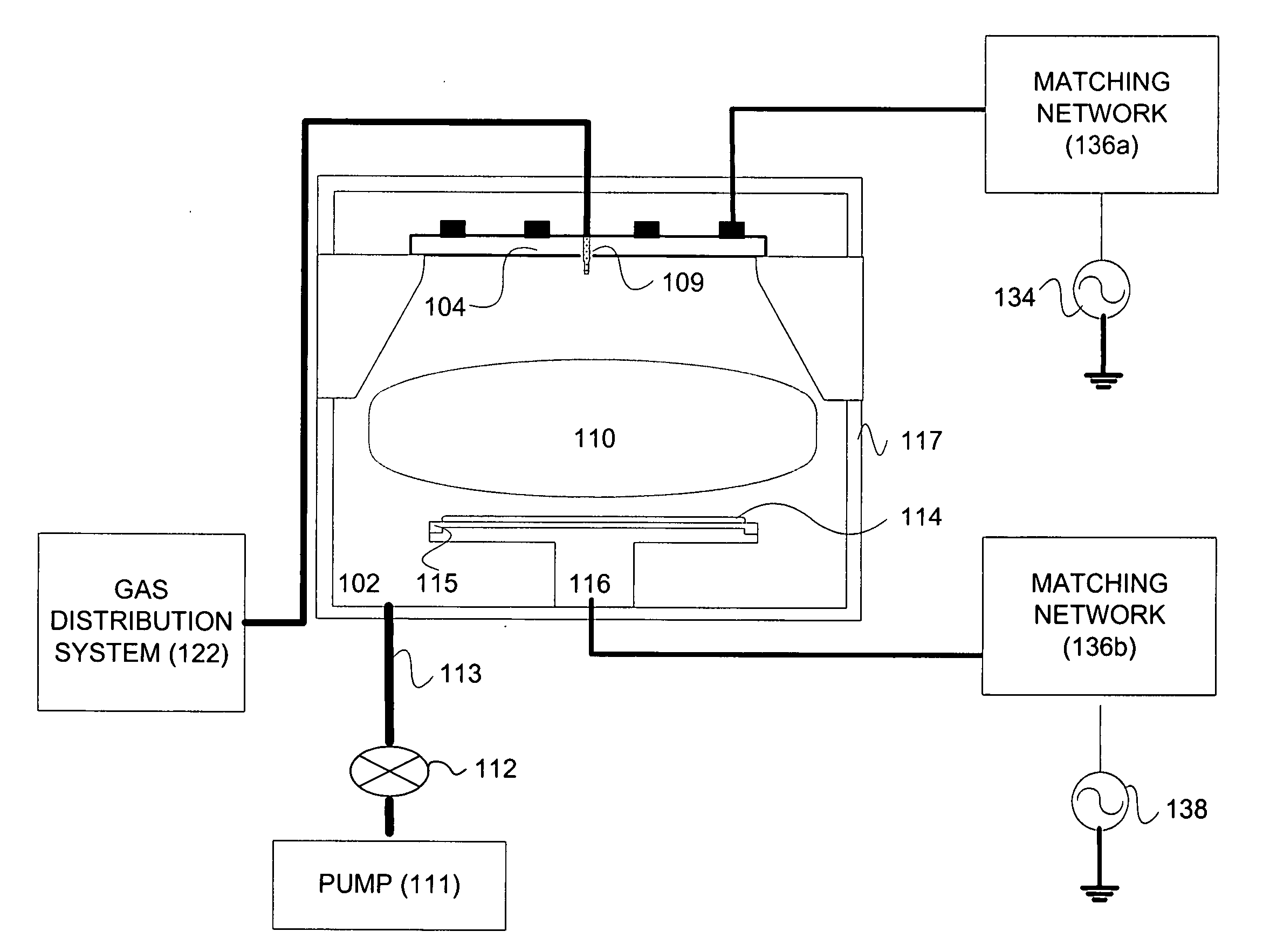
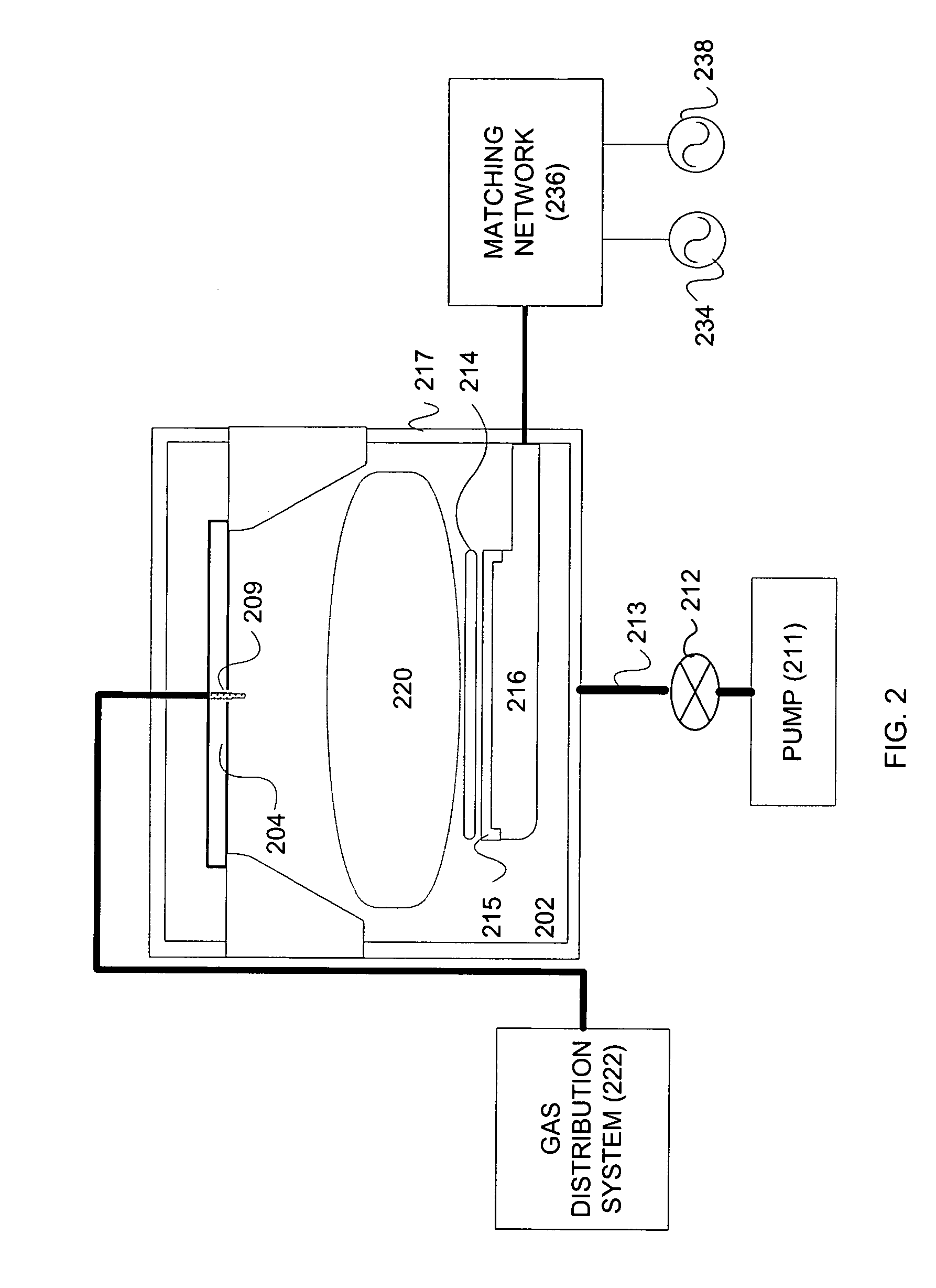
[0033] In general, as previously described, worker safety regulations often mandate that plasma processing manufacturing equipment include activation prevention capability, such as a lockout / tagout mechanism. Generally a lockout is a device that uses positive means such as a lock, either key or combination type, to hold an energy-isolating device in a safe position. A tagout device is ge...


PUM


Abstract

An optimized activation prevention assembly for a gas delivery system is disclosed. The apparatus includes a pneumatically operated valve assembly. The apparatus also includes a toggle switch mechanically attached to the pneumatically operated valve assembly, the toggle switch includes a toggle arm, the toggle arm being positioned in one of an activation zone and a deactivation zone, wherein when the toggle arm is positioned in the activation zone, the pneumatically operated valve is activated, and wherein when the toggle arm is positioned in the deactivation zone, the pneumatically operated valve is deactivated. The apparatus further includes an activation prevention mechanism attached to the toggle switch, wherein when the activation prevention mechanism being configured for preventing the toggle arm from being repositioned from the deactivation zone to the activation zone without at least bypassing a lockout function of the optimized activation prevention mechanism.

Description

CROSS-REFERENCE TO RELATED APPLICATIONS [0001] This application claims priority from U.S. Provisional Application No. 60 / 689,390 entitled “OPTIMIZED LOCKOUT / TAGOUT ASSEMBLY FOR A GAS DELIVERY SYSTEM” by inventor Mark Taskar (filed Jun. 10, 2005, Attorney Docket No. LMRX-P078P, which is incorporated herein by reference.BACKGROUND OF THE INVENTION [0002] The present invention relates in general to substrate manufacturing technologies and in particular to an optimized activation prevention assembly for a gas delivery system, and methods therefor. [0003] In the processing of a substrate, e.g., a semiconductor wafer, MEMS device, or a glass panel such as one used in flat panel display manufacturing, plasma is often employed. As part of the processing of a substrate (chemical vapor deposition, plasma enhanced chemical vapor deposition, physical vapor deposition, etch, etc.) for example, the substrate is divided into a plurality of dies, or rectangular areas, each of which will become an i...

Claims


Application Information

Patent Timeline
IPC IPC(8): F16K35/00
CPCF16K35/06Y10T70/5637Y10T137/0491Y10T137/7069F16K35/00
Inventor TASKAR, MARK
Owner LAM RES CORP
Why Eureka
Eureka Blog
Learn More