Pattern replication with intermediate stamp

a technology of imprint lithography and transfer process, applied in applications, electric/magnetic/electromagnetic heating, instruments, etc., can solve the problems of reducing replication fidelity, affecting the replication fidelity of imprints, and exhibiting difficulties in the imprint process described above, so as to achieve high replication fidelity, easy industrial application, and the effect of high replication fidelity

Active Publication Date: 2006-12-14
OBDUCAT AB SE
View PDF13 Cites 140 Cited by
  • Summary
  • Abstract
  • Description
  • Claims
  • Application Information

AI Technical Summary

Benefits of technology

[0007] It is an object of the invention to provide a solution for an improved imprint pr...

Problems solved by technology

The imprint process described above exhibits some difficulties, which have to be considered in order to achieve a perfect pattern transfer from the template into the moldable layer covering the substrate.
Even though the dimensional change is small, it may be devastating in an imprint process, since the features of the pattern to be transferred are in the order of micrometers or even nanometers.
The result may therefore be reduced replication fidelity.
Very often an inflexible stamp or substrate material is used, and this can lead to the inclusion of air between stamp and moldable layer whe...

Method used


Image

  • Pattern replication with intermediate stamp
  • Pattern replication with intermediate stamp
  • Pattern replication with intermediate stamp

Examples


example 1

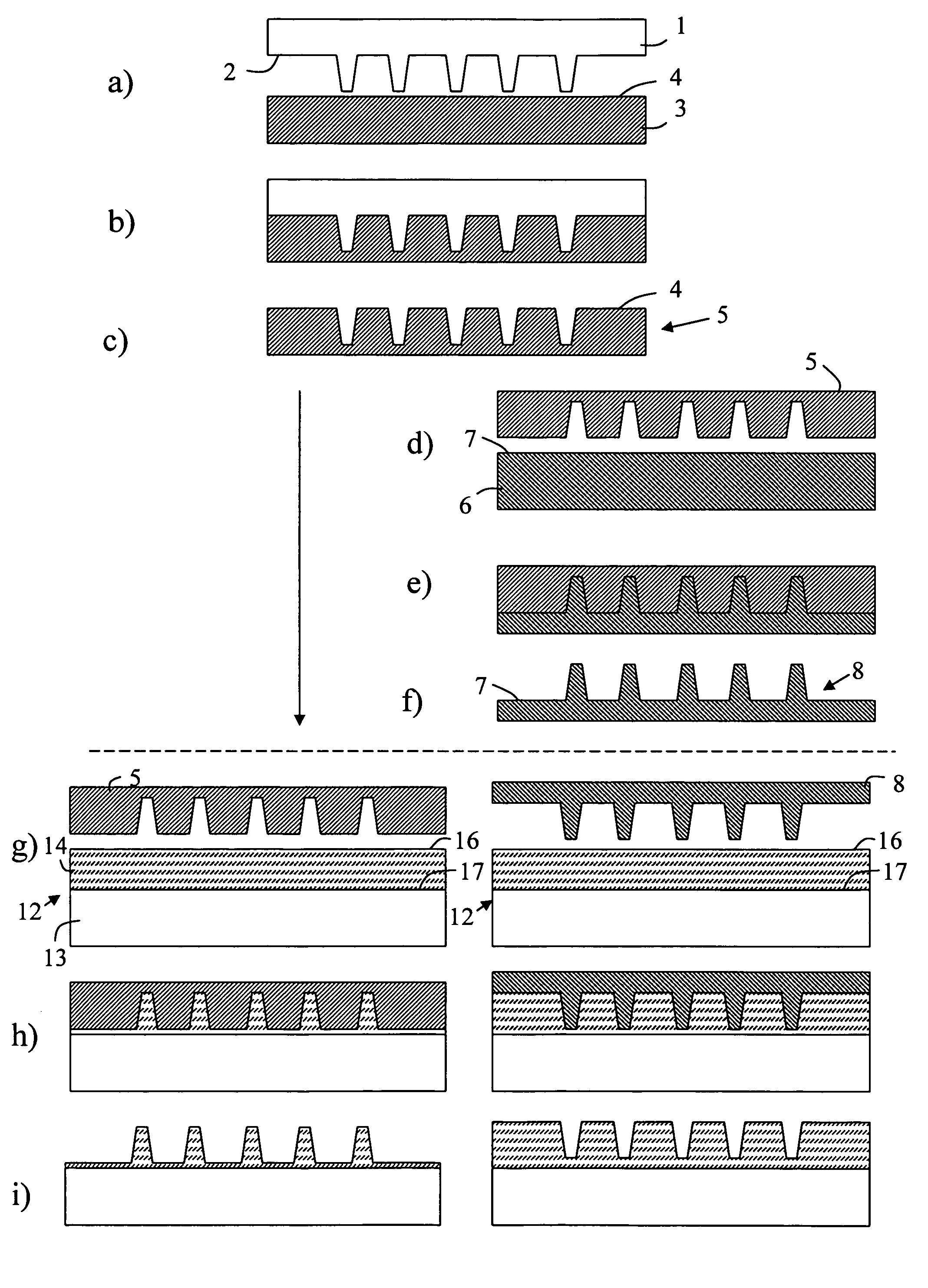
[0170] A nickel template whose surface exhibits a line pattern, having a line width of 80 nm and a height of 90 nm has been imprinted into a Zeonor ZF14 foil at 150° C. and 50 bar for 3 min. None of the surfaces has been treated by any additional coating such as, e.g. anti-adhesion layers. The release temperature was 135° C., at which the Zeonor foil could mechanically be removed from the nickel surface without damaging the pattern of neither the template nor the replica. The Zeonor foil has been used as a new template, which has been imprinted into a 100 nm thick SU8 film. The SU8 film was spin-coated onto a 20nm LOR film, previously spin-coated onto a silicon substrate. Also here, none of the surfaces has been treated by an additional coating, having the purpose to improve the anti-adhesion behaviour between the SU8 film and the Zeonor foil. The imprint was performed at 70° C. and 50 bar for 3 min. The SU8 film was exposed to UV-light for 4 seconds through the optically transparen...

example 2

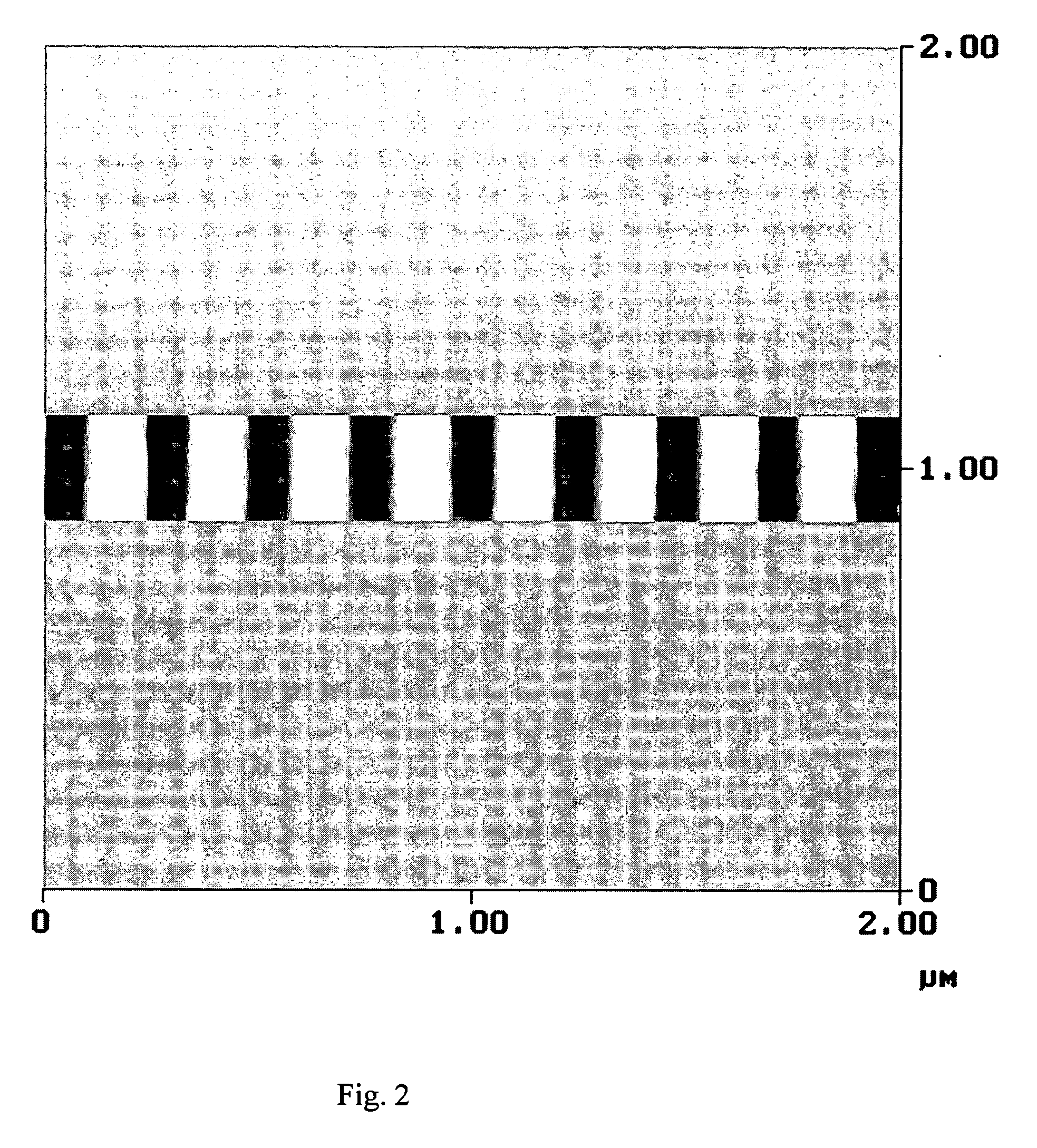
[0171] A nickel template whose surface exhibits a BluRay pattern having structure heights of 100 nm and widths of 150 nm—investigated by AFM—has been imprinted into a Zeonor ZF14 using the same process and the same parameters as already described in Example 1. The Zeonor foil has been used as a new template, which has been imprinted into a 100 nm thick SU8 film. Also here the same process and the same parameters as already described in Examplel have been used. The AFM image of an imprint result in the SU8 film deposited on a silicon wafer is shown in FIG. 3.

example 3

[0172] A nickel template has been used whose surface contains micro-meter patterns with high aspect-ratios ranging from 1-28. The feature size ranges from 600 nm to 12 μm, at a height of 17 μm. The surface has been covered by a phosphate-based anti-adhesion film before the imprint. The nickel template has been imprinted into a polycarbonate foil at 190° C. and 50 bar for 3 min. The surface of the polycarbonate foil has not been treated by an additional coating, having the purpose to improve the anti-adhesion behavior between the Ni template and the polycarbonate film. The release temperature was 130° C., at which the polycarbonate foil could mechanically be removed from the nickel surface without damaging the pattern of neither the template nor the replica. The polycarbonate foil has been used as a new template for an imprint into a Topas foil. The imprint has been performed at 120°C. and 50 bar for 3 min. None of the surfaces has been disposed by an additional coating, having the p...


PUM

PropertyMeasurementUnit
Temperatureaaaaaaaaaa
Timeaaaaaaaaaa
Wavelengthaaaaaaaaaa

Abstract

The invention relates to a two-step process for transferring a pattern from a template (1) to a target surface of a substrate, by creating an intermediate flexible polymer stamp (5) from the template in a primary step, and then using the polymer stamp to make an imprint in a radiation-sensitive moldable layer on the target surface in a secondary step. In the secondary step, the process steps of pressing the polymer stamp and the substrate against each other, UV exposure of the moldable layer through the polymer stamp, and postbaking of the radiated moldable layer, are all performed at a control constant temperature, in order to eliminate damages to the pattern created in the moldable layer caused by thermal expansion effects.

Description

[0001] FIELD OF THE INVENTION [0002] The present invention relates to a pattern transfer process for imprint lithography, which involves a process for transferring a pattern from a template having a structured surface to a target surface of a substrate. More particularly, the invention relates to a two step process in which a replica of the template pattern is formed in or on a flexible polymer foil by imprint to obtain an intermediate polymer stamp, where after the polymer stamp is used in a secondary step to imprint the pattern in a moldable layer applied to the target surface of the substrate. In the secondary step, the imprint process makes use of radiation to solidify the moldable layer under pressure at a controlled constant temperature. BACKGROUND [0003] One of the most powerful techniques for reproducing nanostructures—i.e. structures in the order of 100 nm or smaller—is nanoimprint lithography (NIL). In nanoimprint lithography an inverted copy of the surface pattern of a te...

Claims


Application Information

Patent Timeline
IPC IPC(8): B29C59/02B29C35/08
CPCB29C33/3857B29C35/0888B29C59/022B29C59/026G03F7/0002B29C2059/023B82Y10/00B82Y40/00B29C2035/0827
Inventor HEIDARI, BABAKLOFSTRAND, ANETTEBOLMSJO, ERIKTHEANDER, ERIKBECK, MARC
Owner OBDUCAT AB SE
Why Eureka
Try Eureka