Superconducting Acyclic Homopolar Electromechanical Power Converter

a technology of electromechanical power converter and superconducting magnet, which is applied in the direction of superconducting magnets/coils, magnetic circuit rotating parts, and shape/form/construction of magnetic circuits, etc. it can solve the problems of lack of interest, not being investigated or pursued, and not being relevant whether the cyclic apparatus is cyclic, so as to reduce the physical dimensions, and reduce the large i2r losses

Inactive Publication Date: 2006-12-14
DYNAMO CAPITAL
View PDF39 Cites 13 Cited by
  • Summary
  • Abstract
  • Description
  • Claims
  • Application Information

AI Technical Summary

Problems solved by technology

Further, it is not at all relevant whether the cyclic apparatus utilizes or produces direct current or alternating current, as all cyclic machines are inherently dependant on time-variant electrodynamic interactions, and as such all cyclic machines are all based on alternating current or a form of time varying current.
Faraday's original homopolar / acyclic “electromagnetic rotator” effect was not investigated or pursued as a potential electric motor, primarily because of the large amount of DC current it required in order to operate due to its very low impedance.
This lack of interest persisted in spite of the fact that the Faraday electromagnetic rotator required no complicated switching mechanism such as the solenoids used in the reciprocating “electric motors” of the time.
Similar complicated switching mechanisms still exist in many of the direct current machines of today.
Faraday's original homopolar generator was also not pursued as a potential electric generator, once again because it produced large amounts of DC current at low voltages due to it's characteristic low impedance.
By about 1920, current collector brush and slip-ring difficulties such as brush and slip-ring voltage drops and I2R losses had halted acyclic development, and the acyclic machine had been overtaken by commutated direct current machinery and later even more so by alternating current generators (alternators) due to their operating safety, reliability and economy.
The Group 3 related art topologies and apparatus fail, however, to achieve the series summation of induced electromotive force (generator action) or produced magnetomotive force (motor action.)
Due to this unfortunate outcome, Strohm's later attempts at the series summation of a plurality of said translating conductive elements will most likely also fail.
In U.S. Pat. No. 5,977,684 to Lin, there will be a lack of desired induced electromotive force (or produced magnetomotive force) due to the fact that the uniform / symmetric axial magnetic flux field will not co-rotate at the input shaft angular velocity, but rather, it will appear to be stationary in the machines rotational (non-inertial) reference frame.
In summary, for the cases of related art pertaining to the class of electromechanical power converters termed as being of acyclic topology (and homopolar), the methods known and disclosed for series summation as in Group 2 are mostly impractical, and those known and disclosed as in Group 3 are not viable, and have thus contributed to maintaining the image of the acyclic homopolar converter as solely a low-impedance device.
However, there are still other problems to overcome.
The first obstacle against the widespread use of acyclic (homopolar) machines has been the need for a large number of brushes and brush holders (due to the still very high currents to be handled because of low rotor impedance.)
The second obstacle is a very low machine voltage (or rotor impedance), due to the low voltage (electromotive force) per current “turn” or path.
Essentially, Levi categorically states that the inherent problem of “bucking” or electromotive force cancellation in series connections cannot be overcome in homopolar machines, hence the subsequent diversion to heteropolar machinery (those producing AC).
However, we also note his statement of several unarguable peculiarities and advantages exhibited even by the known classical low-impedance homopolar structures.
Further, to the inventors knowledge, there are no known acyclic methods or apparatus which provide or utilize “flux isolation” in order to eliminate the reverse magnetomotive force produced in certain portions of series connected conductors when such an acyclic apparatus is used as a motor.

Method used


Image

  • Superconducting Acyclic Homopolar Electromechanical Power Converter
  • Superconducting Acyclic Homopolar Electromechanical Power Converter
  • Superconducting Acyclic Homopolar Electromechanical Power Converter

Examples


Embodiment Construction

[0085] For a general understanding of the present invention, reference is made to the drawings. In the drawings, like reference numerals have been used throughout to designate identical elements.

Overview of Electrodynamic Concepts

[0086] A brief overview of electrodynamic concepts is presented here to fully enable one skilled in the art to make and use the invention.

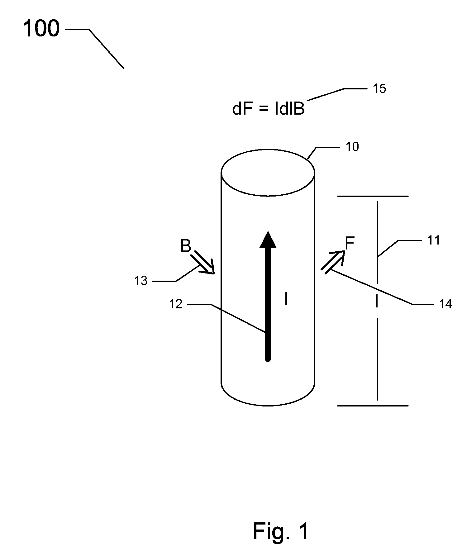
[0087] Shown in FIG. 1 is an illustration of the classical electrodynamic concept of current flow produced magnetomotive force (MMF) over the length of a conductive element located within a uniform perpendicularly applied magnetic field. In this figure, there is a conductive element 10, of length “l”11, said conductive element 10 having a current flow “I”12 therein along its length “l”11, and being situated in a uniform externally applied magnetic (B) field 13. The current flow “I”12 (which is due to a current density J comprised of moving charge carriers, nominally q- or electrons in this case) experiences a net forc...


PUM


Abstract

An acyclic homopolar electromechanical power converter that uses superconducting series connected rotor elements for series summation of magnetomotive and electromotive force. The novel rotor assembly comprises a plurality of conductor elements connected in series by superconducting series connections. The behavior of the superconducting series connections provides a form of flux isolation and series summation of forces that has heretofore been impossible in electromechanical power converters. The superconducting series connections further modify the rotor impedance of an acyclic homopolar electromechanical power converter to provide long needed improvements to acyclic homopolar electromechanical power converter designs.

Description

CROSS-REFERENCE TO RELATED PATENT APPLICATIONS [0001] This application claims the benefit of the filing date of U.S. Provisional patent application No. 60 / 688,890 filed on Jun. 8, 2005. BACKGROUND OF THE INVENTION [0002] 1. Field of the Invention [0003] This invention relates generally to electromechanical power converters, and more particularly to improvements to acyclic homopolar electromechanical power converters. [0004] 2. Description of the Related Art [0005] For a general understanding of the present invention, the following brief background of electromechanical power converters, acyclic machinery, and a historical perspective of electromagnetic machinery is presented. [0006] The creation of magnetomotive force (MMF) in electrical conductor assemblies in the presence of a magnetic field by the flow of current in the electrical conductor assemblies causes translation of the electrical conductor assemblies with respect to the magnetic field. An apparatus used to produce a motive...

Claims


Application Information

Patent Timeline
Patent Type & Authority Applications(United States)
IPC IPC(8): H02K1/22H02K9/00
CPCY02E40/627H02K55/06Y02E40/60
Inventor BLUM, DIETER WOLFGANG
Owner DYNAMO CAPITAL
Why Eureka
Try Eureka