Method and system for estimating motion and compensating for perceived motion blur in digital video

a technology of digital video and motion blur, applied in the field of image processing, can solve problems such as noise and the formation of after-images on the human retina, and achieve the effect of increasing the sharpness of digital video

Active Publication Date: 2006-12-14
138 EAST LCD ADVANCEMENTS LTD
View PDF19 Cites 134 Cited by
  • Summary
  • Abstract
  • Description
  • Claims
  • Application Information

AI Technical Summary

Benefits of technology

[0023] combining each error pixel and its respective pixel in the initial guess frame thereby to update the guess frame and compensate for blur.
[0066] The methods and systems described herein provide the benefits of increased sharpness in digital video displayed on a hold-type display, such as for example an LCD device, without suffering excessive noise amplification as is common in many known inverse filtering methods and without requiring modification of the hold-type display hardware itself. Furthermore, by grouping pixels and clustering motion vectors, prominent global and local object motion in the frame for use during pre-compensation for the perceived motion blur can be recovered quickly.

Problems solved by technology

The perceived blur is also caused in part by prolonged light emission inherent in the sample-and-hold driving technique commonly employed by LCD devices, which results in formation of after-images on the human retina.
As with other known inverse filtering methods, however, noise can be problematic.

Method used


Image

  • Method and system for estimating motion and compensating for perceived motion blur in digital video
  • Method and system for estimating motion and compensating for perceived motion blur in digital video
  • Method and system for estimating motion and compensating for perceived motion blur in digital video

Examples


Embodiment Construction

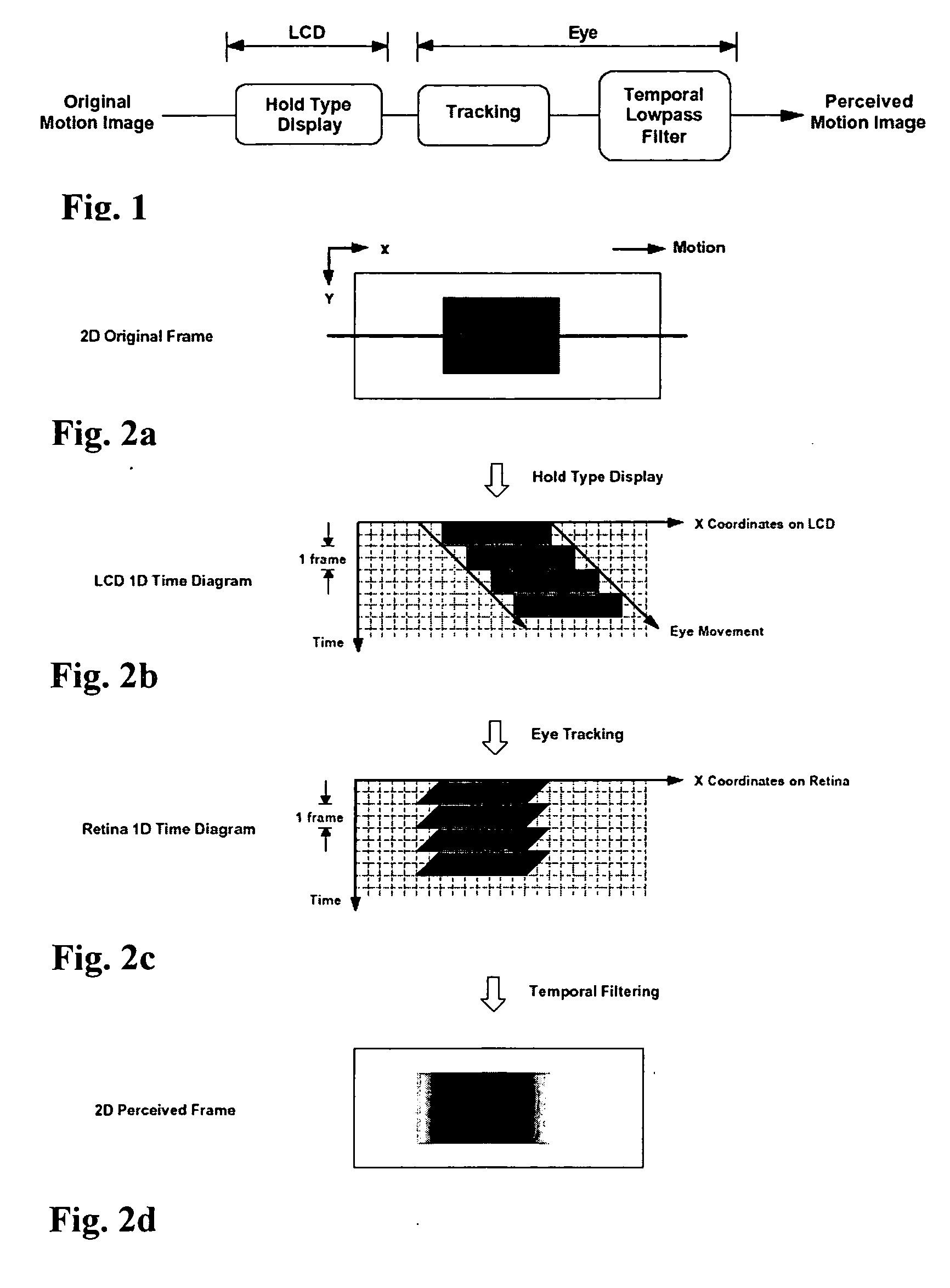
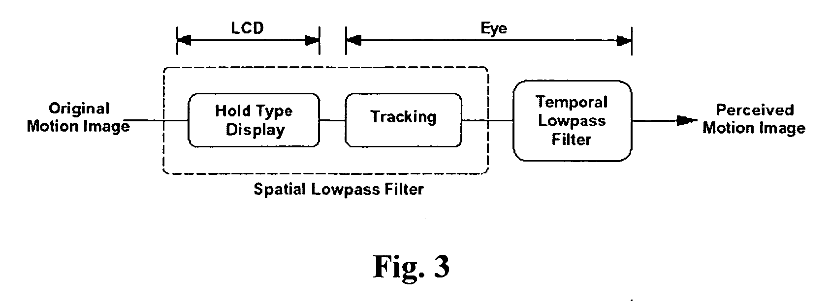
[0089] For ease of understanding, perceived blur in a digital video image caused by a hold-type display such as an LCD device that uses a sample and hold display format will firstly be discussed. Turning to FIG. 1, a schematic diagram showing perceived blur in a digital video image frame resulting from the LCD device and the motion perception mechanisms of the human visual system is shown. The following assumes that the frame rate of the LCD device is sufficiently high to permit perfect temporal integration into the human visual system within one frame interval. It has been shown by D. C. Burr, in the publication entitled “Temporal Summation of Moving Images by the Human Visual System” (Proceedings of the Royal Society of London B, 221(1184), pp. 321-339, 1981) that this condition is satisfied with frame rates of 60 Hz or higher. The following also assumes that the human eye can perfectly track region movement across the LCD device. It has been reported by S. Daly in the publication...


PUM


Abstract

A method for compensating for perceived blur due to motion between a current frame and a previous frame of a digital video sequence comprises estimating a motion vector between the frames for each of a plurality of pixel blocks in the current and previous frames. A cluster motion vector is then estimated for each of a plurality of clusters of the motion vectors based on one of vectors in each cluster and motion vectors in proximate clusters. The cluster motion vector of its corresponding cluster is allocated to each pixel in the current frame. An initial guess frame is generated based on the current frame and pixels in the guess frame are blurred as a function of their respective allocated cluster motion vectors. Each blurred pixel is compared with a respective pixel in the current frame to generate an error pixel for each respective pixel. Each error pixel is blurred and weighted and then each error pixel and its respective pixel is combined in the initial guess frame thereby to update the guess frame and compensate for blur. A system and computer program for perceived blur compensation is also provided.

Description

CROSS-REFERENCE TO RELATED APPLICATION [0001] This application claims the benefit under 35 U.S.C. 119(e) of U.S. Provisional Patent Application Ser. No. 60 / 689,808, filed on Jun. 13, 2005, the content of which is incorporated herein by reference.FIELD OF THE INVENTION [0002] The following relates generally to image processing and more particularly to a method and system for estimating motion in digital video and to a method and system for compensating for perceived motion blur in digital video displayed by hold-type displays. BACKGROUND OF THE INVENTION [0003] It is well known that moving objects in digital video displayed on a hold-type display device such as a liquid crystal display (LCD) can appear blurry to an observer. The perceived blur is known to be caused in part by the relatively slow LC response of the liquid crystal cells. When compared with an impulse-type device such as a cathode ray tube (CRT) device, for example, an LCD device has a much slower brightness transition ...

Claims


Application Information

Patent Timeline
Patent Type & Authority Applications(United States)
IPC IPC(8): H04N11/02H04N7/12H04B1/66H04N11/04
CPCG06T7/2013G06T2207/10016G09G2320/0257G06T2207/20201G09G2340/16G06T5/003G06T5/50G09G2320/0261G06T7/223H04N5/208G09G3/20
Inventor POON, EUNICE
Owner 138 EAST LCD ADVANCEMENTS LTD
Why Eureka
Try Eureka