
Footwear sole

a technology for soles and shoes, applied in the field of shoes, can solve the problems of eva, conventional closed and open cell foams, and the sole may lose its resiliency over time, and achieve the effects of extending the cushioning life of the midsole, increasing vertical stiffness, and easy tuning

Inactive Publication Date: 2006-12-21
WOLVERINE WORLD WIDE
View PDF9 Cites 10 Cited by
  • Summary
  • Abstract
  • Description
  • Claims
  • Application Information

AI Technical Summary

Benefits of technology

"The present invention provides a shoe with a unique sole that can be easily adjusted to provide the desired support profile. The sole includes a support layer between the outsole and midsole, and a heel wedge can be added for additional support. The insert has multiple support tubes that can be adjusted to provide the desired support characteristics, including an arch portion for protection and a forefoot extension for more rigidity. The struts help to centering the foot on heel strike. The invention provides a durable and adjustable shoe that can improve performance and comfort."

Problems solved by technology

In conventional footwear, the midsole (as well as the other sole components) may begin to lose its performance over a relatively short period of time.
Degradation of the sole material can cause the sole to lose its resiliency over time, particularly in regions of high and repeated impact, such the heel.
For example, conventional closed and open cell foams, such as EVA, have a relatively short life as the material naturally breaks down over relatively short periods of use.
Conventional foam materials are also susceptible to temperature changes, which can cause the resiliency of the foam to vary noticeably softer in higher temperatures.
As a result, temperature can have a significant adverse affect on the support characteristics of a sole manufactured from conventional foam materials.

Method used


Image

  • Footwear sole
  • Footwear sole
  • Footwear sole

Examples


Embodiment Construction

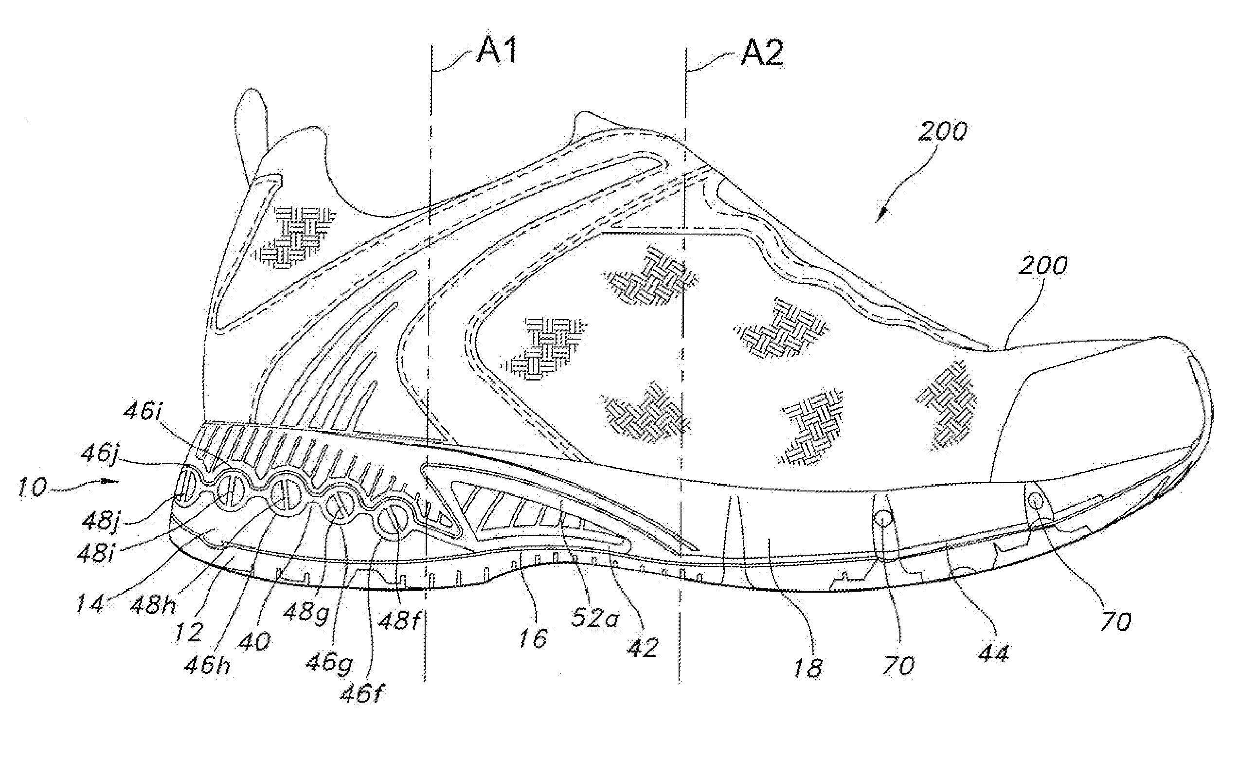
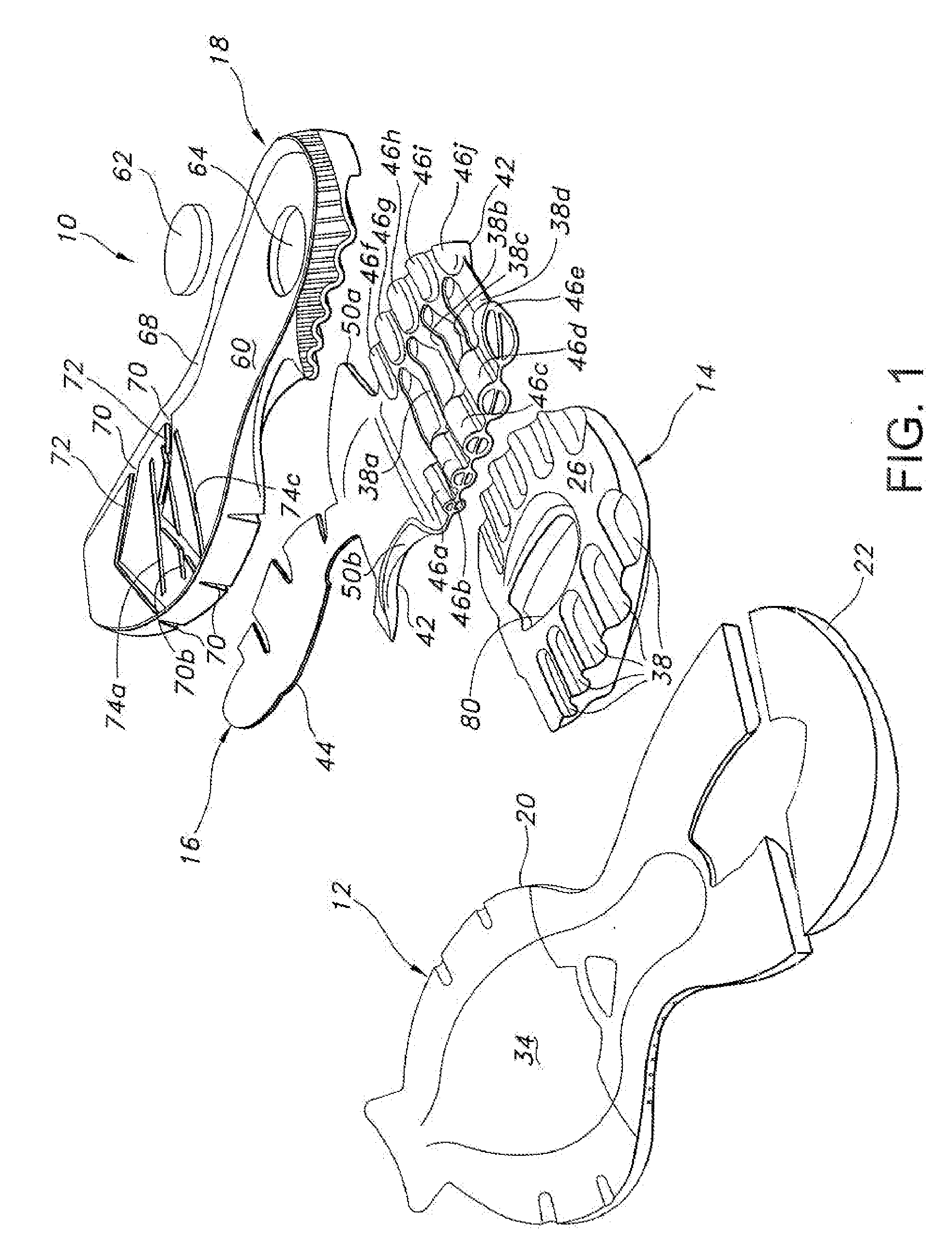
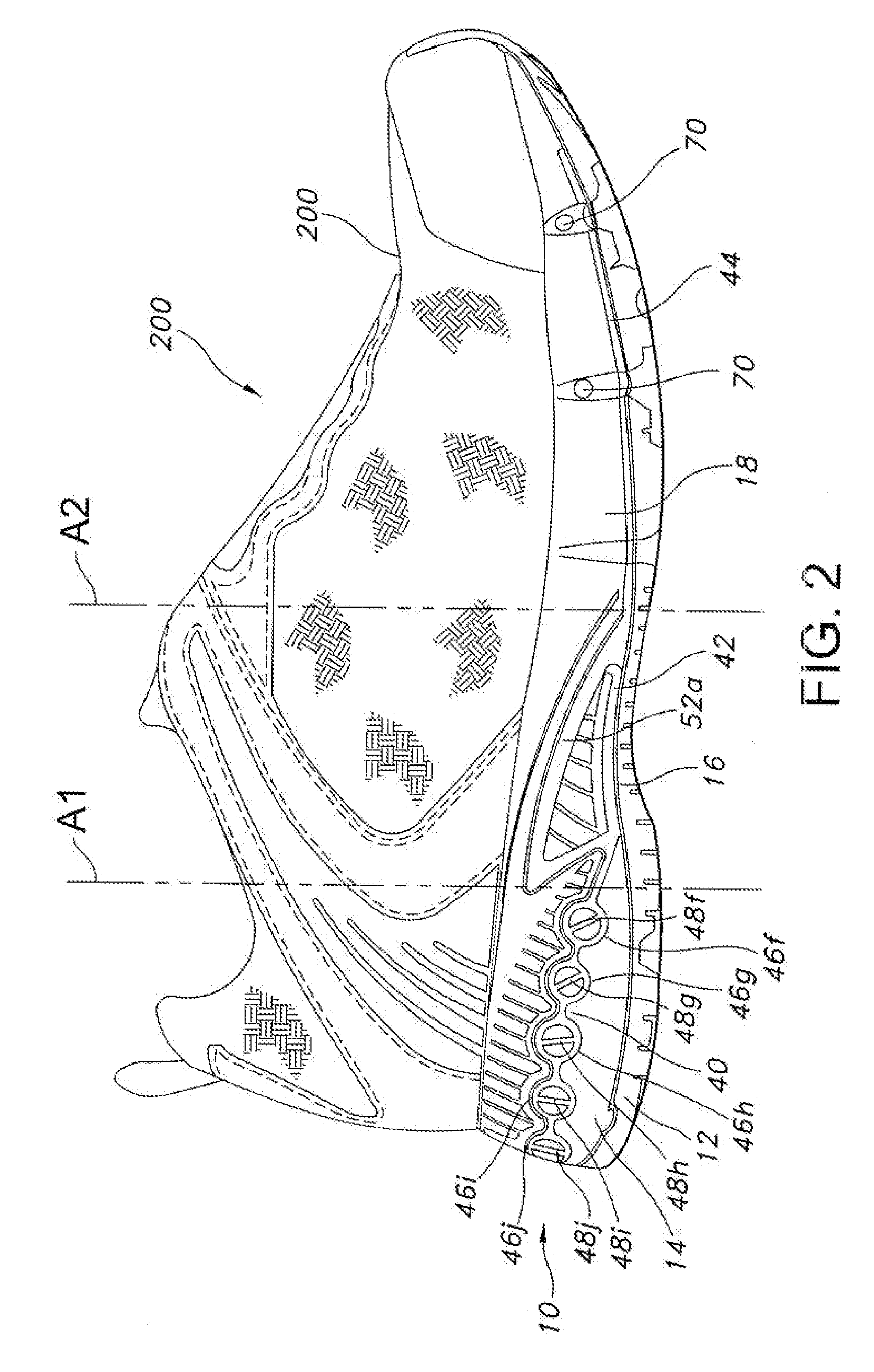
[0024] A footwear sole manufactured in accordance with an embodiment of the present invention is shown in FIG. 1, and generally designated 10. The footwear sole 10 generally includes an outsole 12, a heel wedge, 14, an insert 16 and a midsole 18. The sole 10 may be incorporated into an article of footwear, such as shoe 200 shown in FIGS. 2. The shoe 200 may include an upper 202 that is affixed to the sole 10. The shoe 200 may also include a foot bed (not shown) that is removably fitted into the upper 202 atop of the sole 10. The insert 16 may include support tubes 46a-j with internal webs 48a-j that are configured to control the support profile of the sole 10. Although the present invention is described in connection with a conventional standard height running or trail running shoe 200, the present inventions not limited to use in shoes of that type. The present invention is well-suited for use in essentially any type of sole and can be incorporated into essentially any type of foot...


PUM


Abstract

A sole for an article of footwear having an insert that includes a slot for receiving a gaiter strap. In one embodiment, the insert includes a plurality of support tubes that include internal webs configured to control the support characteristics of each support tube. In one embodiment, a first plurality of support tubes is disposed along the medial side of the sole in the heel region and a second plurality of support tubes is disposed along the lateral side of the sole in the heel region. The insert may include an arch portion that extends through and provides support to the arch region of the sole. The arch portion may define a slot to receive a gaiter strap. The insert may further include a forefoot extension that extends forwardly from the arch along the medial side of the sole. In one embodiment, the sole may include a heel wedge disposed below the insert in the heel region such that the support tubes are supported upon a relatively resilient material. In one embodiment, the insert may include struts that interconnect the medial and lateral support tubes.

Description

BACKGROUND OF THE INVENTION [0001] The present invention relates to footwear, and more particularly to a sole construction for an article of footwear. [0002] There is a continuing effort to provide ever more comfortable footwear. Running shoes, as well as other footwear, have undergone tremendous evolutionary advances in technology over the past 20 years. Many of the technological advances have occurred in the midsole. In most footwear, the mid sole functions as the “suspension system” of the sole and it often provides both protective cushioning and a stable platform for the wearer's foot. Variations in the characteristics of the midsole can have a dramatic affect on the performance of the shoe. In an effort to provide improved performance, it is often desirable to vary the support characteristics of the sole from one region to another. For example, it may be desirable to provide a higher density material in the heel and a lower density material in the forefoot. A higher density mat...

Claims


Application Information

Patent Timeline
Patent Type & Authority Applications(United States)
IPC IPC(8): A43B13/18A43B13/20
CPCA43B7/144A43B13/206A43B13/186A43B13/181
Inventor SCHOENBORN, MARY L.REARDON, DONALD R.
Owner WOLVERINE WORLD WIDE
Learn More