
Potato Planter Improvement to Reduce Skips and Rolling

Inactive Publication Date: 2006-12-21
WOLLMAN ALBERT E +1
View PDF16 Cites 25 Cited by
  • Summary
  • Abstract
  • Description
  • Claims
  • Application Information

AI Technical Summary

Benefits of technology

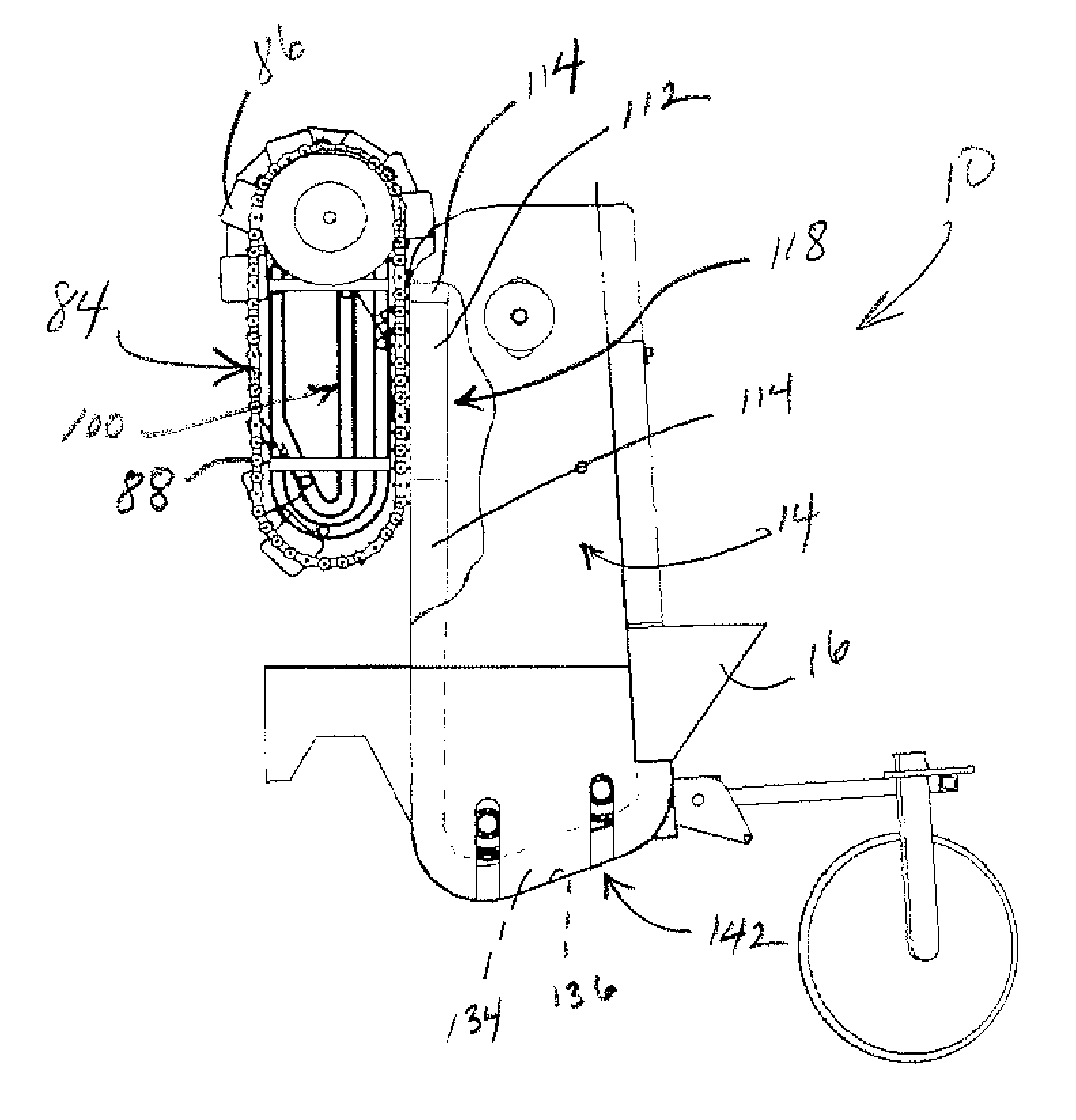
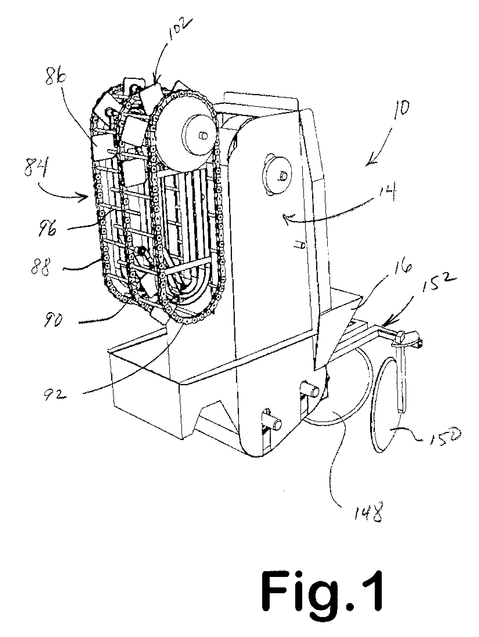
[0019] The design disclosed here modifies the belt and cup arrangement or configuration on the typical machine. In the design disclosed here, the belt is modified by widening it and adding another two rows of cups, one on each side of the two rows in the center. The two rows in the center serve or function as the primary seed conveyor in the same way as conventional machines. That is, they normally pick up seeds and then drop them in the ground. The extra row of cups, one on each side of the primary cups, function to effectively create a secondary conveyor. In essence, the secondary conveyor delivers replacement seeds into the primary conveyor seed cups when they fail to either pick up seeds from the seed bin, or lose them after picking them up, due to machine vibration or similar factors.
[0020] The extra cups, which are at times referred to as “seed holders” or “secondary cups” here, pick up seeds in the same way as the primary cups and travel adjacent and parallel to the primary cups, along the same endless conveyor belt path. As described below, they have a different physical shape for the purpose of facilitating the transfer of replacement seeds.
[0027] There will be instances when secondary cups are also empty after passing through the seed bin for the same reasons that primary cups are empty. However, the probability is low that both a primary and adjacent secondary cup will leave the seed bin empty. As a consequence, the replacement method described here should reduce or avoid the possibility of a planting skip. Moreover, it represents a relatively simple and low cost design modification to existing cup-style planters.
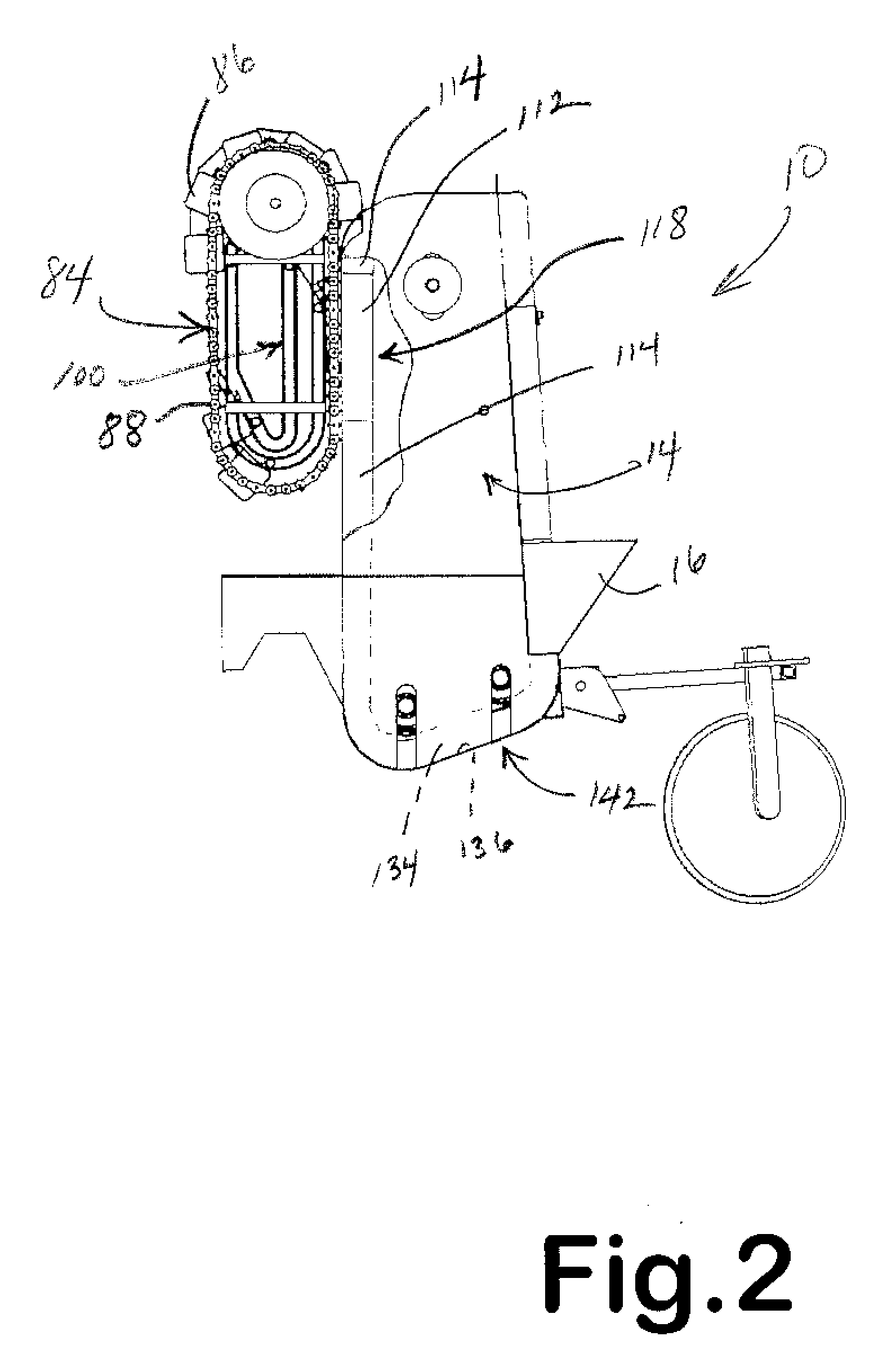
[0033] The belt on modern cup-style planters follows an oval track that is defined by a roller at the top and another one of equal size at the bottom. In accordance with the improvement described here, a second, lower roller is added that causes the belt to travel a path that deviates from oval toward slightly triangular. The lower leg or side of the triangle is close to parallel to the ground and the upstanding conveyor is close to perpendicular to the ground. It might be possible to accomplish the same dynamic change in momentum by using a single, large roller at the lower end of the belt. Either way, the concept is to slow down the velocity of potato seeds relative to the ground before or as they exit the machine—which means that their momentum will be reduced when they hit the furrow.
[0034] The above improvement allows tractor speed to be theoretically increased to some higher limit before seed rolling in the furrow again becomes a problem. While this may seem like a subtle change, the productivity improvements can be significant. If tractor ground speed can be increased from 4 to 5 mph, for example, with no resultant loss in seed spacing accuracy, then it can mean significant time savings that will be measured in planting days for commercial potato growers who plant large acreages—and for a very low-cost design change.

Problems solved by technology

However, it also has a complex system of individual vacuum tubes, each one of which needs to be connected to a vacuum source.
This higher level of mechanical complexity makes the machine more expensive to use.
Machine maintenance, in particular, is more expensive for this machine relative to others.
If a seed is not planted where a seed could or should be planted, then the potato grower loses a unit of production.
A known problem with seed planting machines is that they do not achieve 100% perfection in seed planting.
Because the planting machine either fails to “stick” to a potato seed well enough (e.g., the “pick” or “vacuum” type machines), or a conveyor cup fails to pick up a potato from the bin in the other kind of machine, potato rows are planted with seed “skips” in the row.
For a large grower like WHB, skips of this magnitude effectively create a situation where 500 acres of land went unplanted—which is a significant loss in production.
At the same time, all of the costs for that unplanted acreage are still incurred, because things like irrigation, spraying and harvesting equipment cover all of the ground, in the same way, without distinguishing between planted and unplanted spots.
Losses due to skipping, therefore, directly affect the bottom line in terms of profit.
Differences in the amount of roll, caused by differences in seed shape (e.g., rounded vs. cut surfaces) cause some seeds to be too close together and others to be too far apart.
The end result is plant crowding that causes deformities and, as a consequence, price decreases for the farmer.

Method used


Image

  • Potato Planter Improvement to Reduce Skips and Rolling
  • Potato Planter Improvement to Reduce Skips and Rolling
  • Potato Planter Improvement to Reduce Skips and Rolling

Examples


Embodiment Construction

[0051] Referring now to the drawings, and first to FIG. 1, shown generally at 10 is an improved potato planter constructed in accordance with the invention. The planter 10 is a “cup” or “cup-type” planter. It has a conveyor belt 12 (see, e.g., FIG. 3) that is inside a housing structure 14. A seed bin 16 holds seed potatoes for planting in the field. The conveyor belt 12 is covered with seed holders, or seed cups 18, 30 (FIG. 3), rows of which are also generally indicated by arrows 22, 28 in FIGS. 8 and 9. These cups are bolted to the belt in the same way as existing cup planters.

[0052] It needs to be explained that the drawings that illustrate the conveyor belt 12 do not show all of the cups 18, 30 on the belt. Referring to FIG. 5, for example, which illustrates the upper portion of the belt 12, it can be seen that the illustration shows only the upper part of the belt as being covered with cups. In actual practice, the entire outer surface of the belt 12 will be covered (with cups...


PUM


Abstract

An improved cup-style potato planter that corrects seed “skips.” Cups on a continuous belt conveyor sometimes fail to pick up potato seeds from a bin, or the seeds drop from the cup due to vibration. The design disclosed here puts replacement seeds in empty cups before the conveyor reaches a point in conveyor travel where the seed is supposed to be dropped into the ground.

Description

RELATED APPLICATIONS AND INFORMATION INCORPORATED BY REFERENCE [0001] This specification claims priority on provisional Application Ser. No. 60 / 687,898, filed on Jun. 07, 2005, and provisional Application Ser. No. 60 / 759,078, filed on Jan. 17, 2006.TECHNICAL FIELD [0002] The invention disclosed here relates to a potato seed planter that improves upon seed planting and seed skips, in particular, when potato seeds are mechanically planted in a field row. BACKGROUND OF THE INVENTION [0003] Commercial potato growers favor two or three types of potato seed planting machines. One type is a “pick” style machine that has a spiked wheel that rotates as a tractor pulls the machine over the ground. The spikes on the wheel “stick” into, and pick up, individual potato seeds from a bin. The seeds are dropped in a furrow as the wheel rotates. [0004] A second type of machine is called a “cup” style machine by farmers. The second machine has an upright, endless or continuous conveyor belt that carri...

Claims


Application Information

Patent Timeline
IPC IPC(8): A01C7/18
CPCA01C9/02
Inventor WOLLMAN, ALBERT E.WOLLMAN, MICHAEL J.
Owner WOLLMAN ALBERT E
Learn More