Integrated liquid cooled heat sink for electronic components

a heat sink and electronic component technology, applied in electrical equipment, cooling/ventilation/heating modifications, lighting and heating apparatus, etc., can solve the problem of relatively low air heat capacity and achieve the effect of reducing shipping, handling and installation

Inactive Publication Date: 2006-12-21
COOLIT SYSTEMS INC
View PDF8 Cites 94 Cited by
  • Summary
  • Abstract
  • Description
  • Claims
  • Application Information

AI Technical Summary

Benefits of technology

[0012] The present invention utilizes a single unit to define both the cooling housing and the air cooled heat rejecter to the

Problems solved by technology

However, these electronic devices are increasingly being miniaturized and designed to achieve increase

Method used


Image

  • Integrated liquid cooled heat sink for electronic components
  • Integrated liquid cooled heat sink for electronic components
  • Integrated liquid cooled heat sink for electronic components

Examples


Embodiment Construction

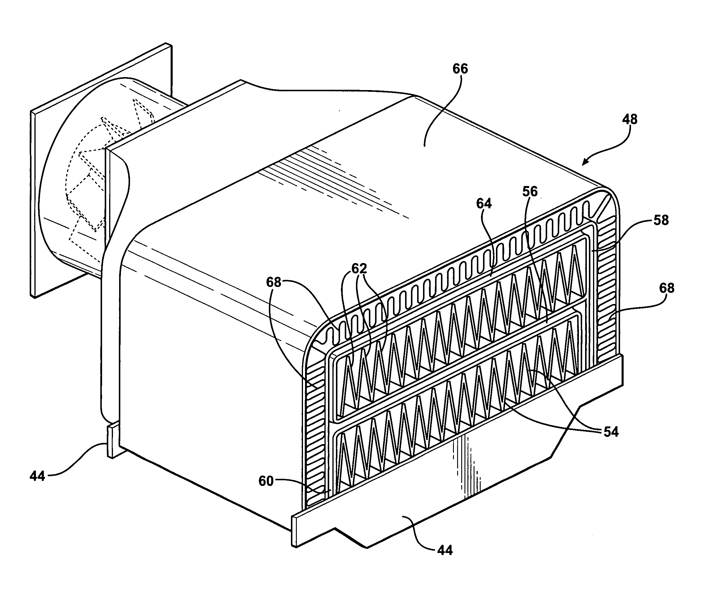
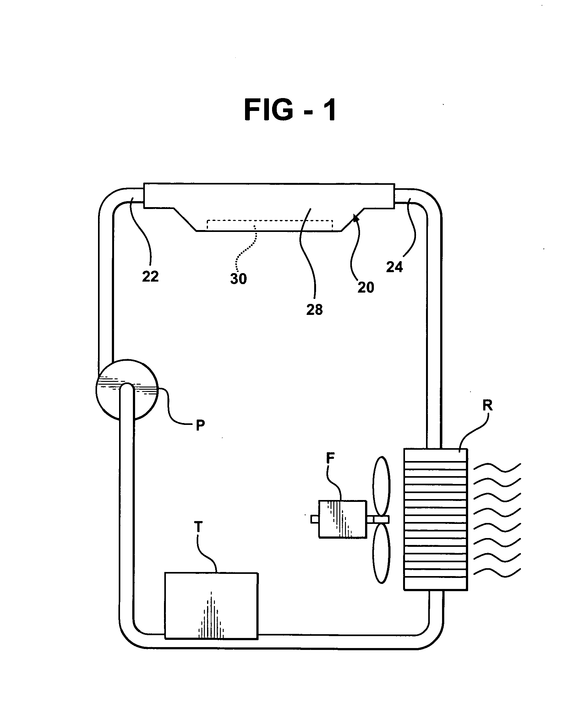
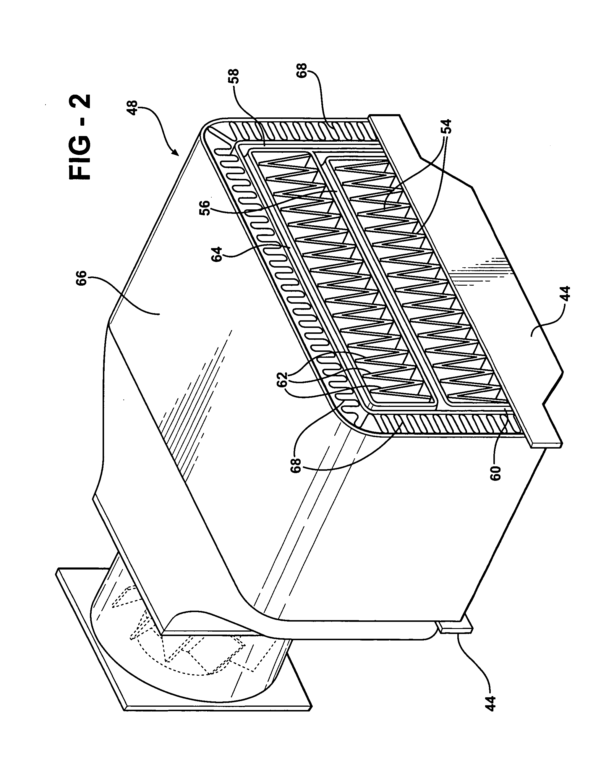
[0019] As alluded to above, the fluid heat exchanger unit of the subject invention incorporates a cooling housing 20 of the type disclosed in the aforementioned co-pending patent applications. The cooling housing 20 includes a liquid coolant inlet 22 and a liquid coolant outlet 24 and an upper portion 26 defining a top or upper wall 27 and a lower portion 28 extending between the liquid coolant inlet 22 and the liquid coolant outlet 24 for establishing a direction of flow from the liquid coolant inlet 22 to the liquid coolant outlet 24. The cooling housing 20 is used to cool an electronic device 30 engaging or secured to the lower portion 28 of the cooling housing 20. The electronic device 30 or component is preferably adhesively secured in a recess 29 in the bottom 40 of the cooling housing 20.

[0020] A partition 32 divides the cooling housing 20 into the upper portion 26 and the lower portion 28 for establishing a direction of flow of liquid coolant in a coolant passage 33 defined...


PUM


Abstract

A fluid heat exchanger unit cools an electronic device with a cooling fluid supplied to an upper portion of a cooling housing. A refrigerant is disposed in a lower portion of the cooling housing for liquid-to-vapor transformation. A partition divides the upper portion of the cooling housing from the lower portion. A heat rejecter is disposed on and above the upper wall of the cooling housing with a first header extending from and in fluid communication with the liquid coolant outlet. A second header extends upwardly from a rejecter outlet. A plurality of first tubes extend between and in fluid communication with the first header and the second header with a plurality of first air fins disposed between the upper wall and the first tubes. A single unit defines both the cooling housing and the air cooled heat rejecter to thereby allow the manufacture of the unit in a single process with the attendant reduction in shipping, handling and installation.

Description

RELATED APPLICATIONS [0001] The subject invention has widespread utility as illustrated in the co-pending application Ser. No. 11 / 040,989 (DP-312789); Ser. No. 11 / 040,321 (DP-311408) and Ser. No. 11 / 040,988 (DP-311409), all filed on Jan. 21, 2005. BACKGROUND OF THE INVENTION [0002] 1. Field of the Invention [0003] A fluid heat exchanger unit for cooling an electronic device. [0004] 2. Description of the Prior Art [0005] Research activities have focused on developing assemblies to efficiently dissipate heat from electronic devices that are highly concentrated heat sources, such as microprocessors and computer chips. These electronic devices typically have power densities in the range of about 5 to 35 W / cm2 and relatively small available space for placement of fans, heat exchangers, heat sink assemblies and the like. However, these electronic devices are increasingly being miniaturized and designed to achieve increased computing speeds that generate heat up to 200 W / cm2. [0006] Heat e...

Claims


Application Information

Patent Timeline
IPC IPC(8): H05K7/20
CPCH01L23/473H01L2924/0002H01L2924/00F28D15/0266
Inventor GHOSH, DEBASHISBHATTI, MOHINDER SINGH
Owner COOLIT SYSTEMS INC
Why Eureka
Try Eureka