Ultra-fine spray-jetting nozzle

a technology of ultra-fine spray jets and spray jets, which is applied in the direction of spray nozzles, burners, lighting and heating apparatus, etc., can solve the problems of difficult clogging of impurities contained in the fluid, and achieve the effects of reducing maintenance times, enhancing productivity, and suppressing the occurrence of clogging of impurities

Inactive Publication Date: 2006-12-21
H IKEUCHI
View PDF7 Cites 15 Cited by
  • Summary
  • Abstract
  • Description
  • Claims
  • Application Information

AI Technical Summary

Benefits of technology

[0046] As described above, the ultra-fine spray-jetting nozzle of the present invention have the construction of suppressing the occurrence of the clogging of the impurities. Thereby it is possible to reduce the number of maintenance times. Thus the ultra-fine spray-jetting nozzle contributes to the enhancement of productivity by utilizing it for industrial use.
[0047] Further the ultra-fine spray-jetting nozzle is capable of reducing a jet sound generated by the nozzle. Thus it is possible to prevent noise from being generated by the nozzle, when an air conditioner or the like on which the nozzle is mounted is used in a quiet environment.
[0048] Even though the ratio of the volume of the gas to that of the liquid is set to less than 1000, the average particle diameter can be reduced to about 10 μm. Therefore it is possible to reduce the cost.

Problems solved by technology

Thus it is possible to make it difficult for impurities contained in the fluid to clog.

Method used


Image

  • Ultra-fine spray-jetting nozzle
  • Ultra-fine spray-jetting nozzle
  • Ultra-fine spray-jetting nozzle

Examples


first embodiment

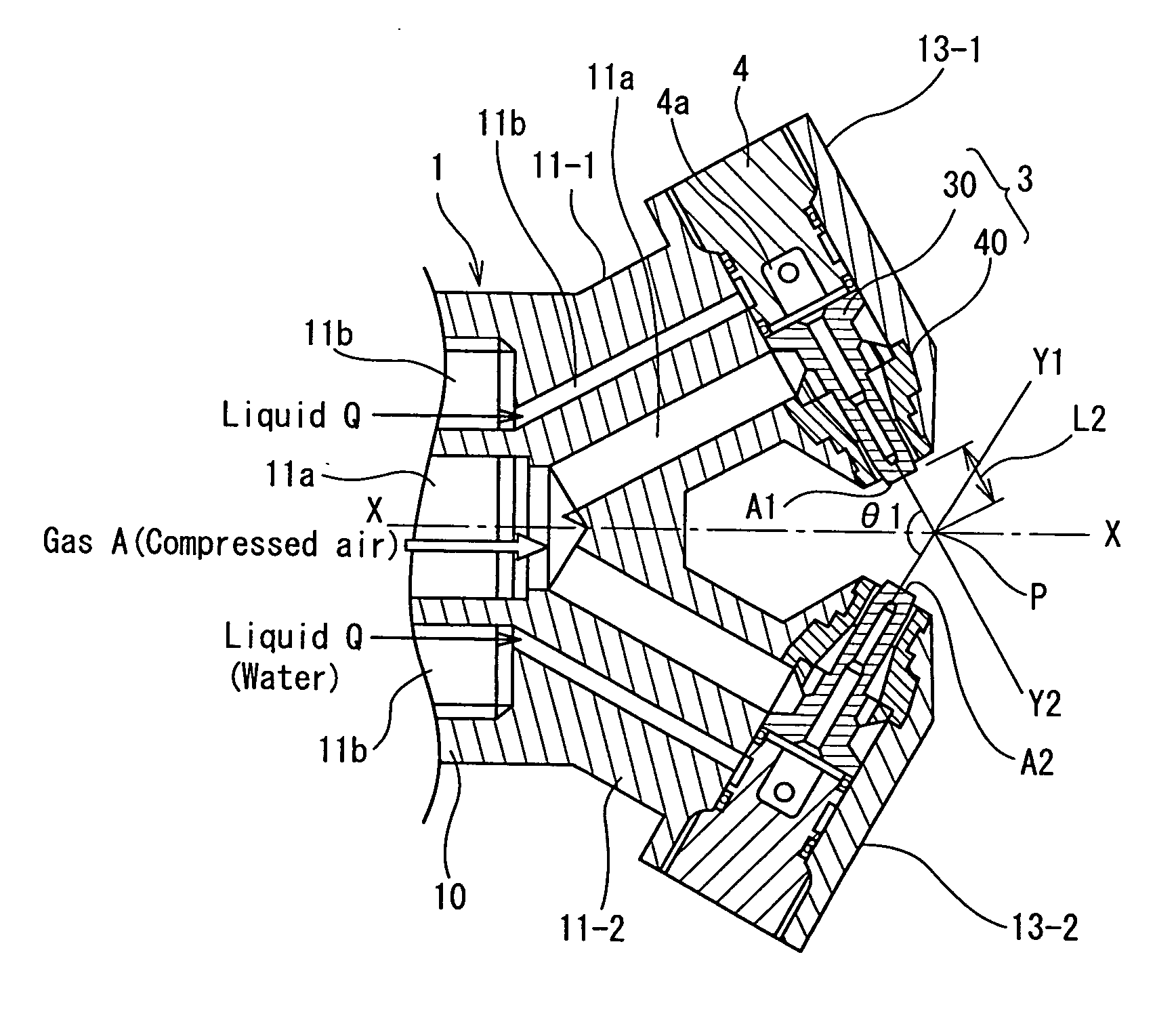
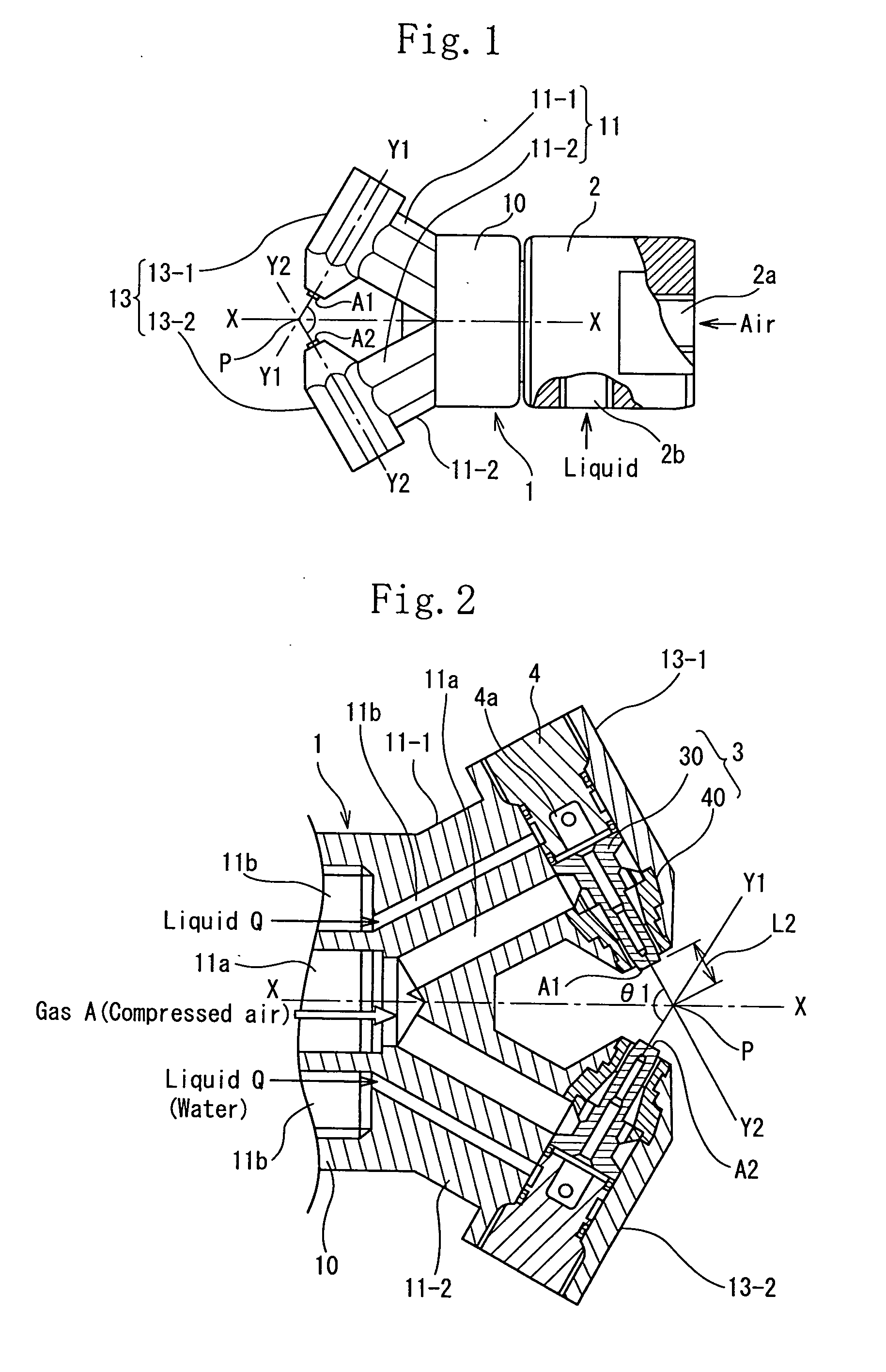
[0067] The nozzle of the first embodiment has a nozzle tip composed a first nozzle tip and a second nozzle tip combined with the first nozzle tip. The nozzle has a nozzle body 1; an adapter 2, removably coupled with a rear end of the nozzle body 1, for supplying the liquid and the gas to the nozzle body 1; and a nozzle tip 3, composed of a first nozzle tip 30 and a second nozzle tip 40, both of which are mounted in a tip-accommodating portion 13 of the nozzle body 1. The first nozzle tip 30 and the second nozzle tip 40 are made of metal. The nozzle body 1 and the adapter 2 are made of resin.

[0068] The nozzle body 1 includes a branch portion 11 (11-1, 11-2) branched in the shape of a character V from a front end surface of a cylindrical portion 10 whose rear end is connected with the adapter 2; and a tip-accommodating portion 13 (13-1, 13-2) disposed at the front end of each branch portion 11 with the tip-accommodating portion 13 inclining with respect to jetting sides thereof in pro...

second embodiment

[0103] Although the construction of the second embodiment causes processing and molding operations for manufacturing the nozzle body to be performed complicatedly, it reduces the number of parts and the number of assembling steps.

[0104]FIGS. 9A through 9D show other embodiments of the separate gas passages.

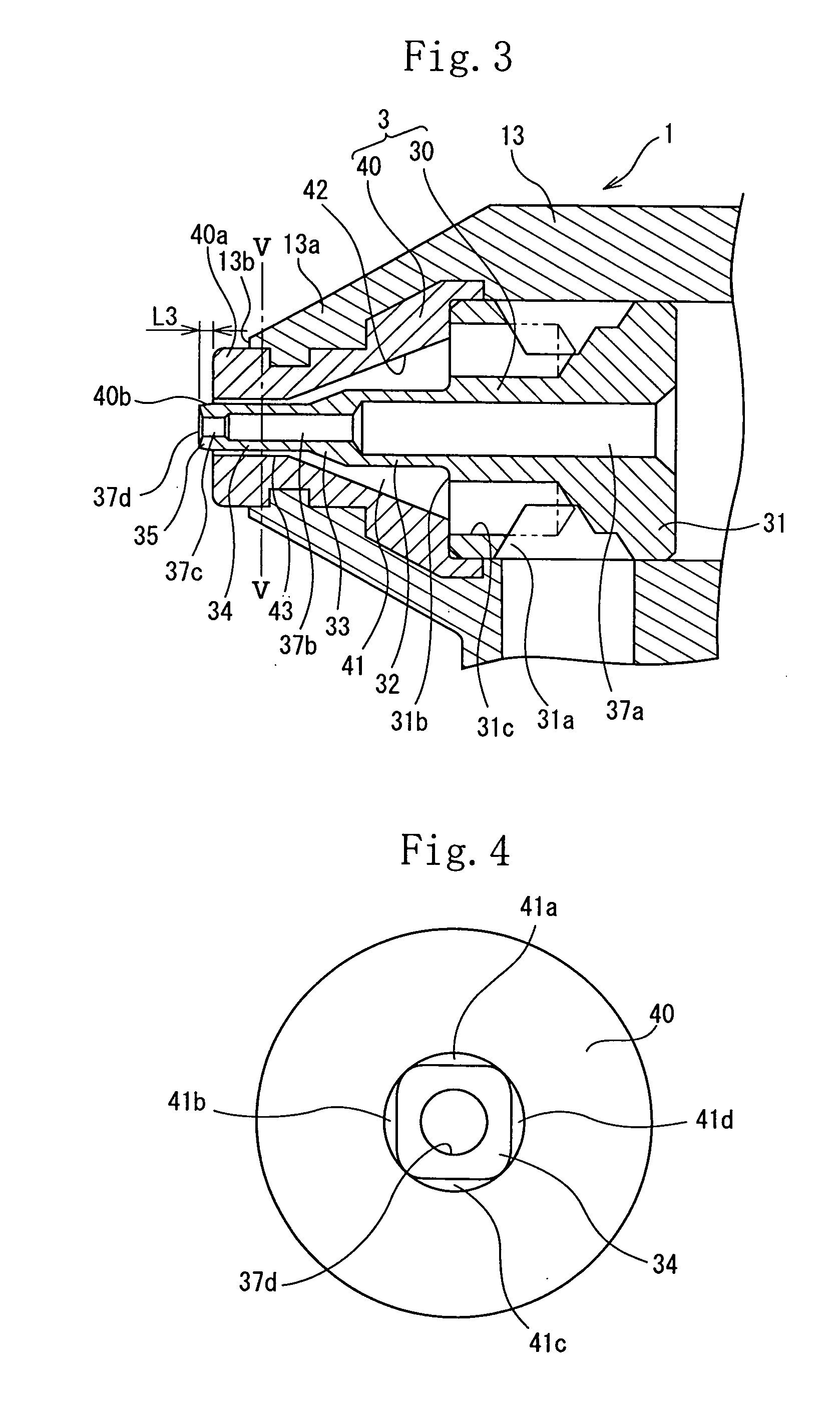
[0105] In the first and second embodiments, the outer configuration of the square pillar portion 34 of the first nozzle tip 30 is sectionally square, and the gas passage is divided into four regions. In the other embodiments, the gas passage disposed at the jetting-port side is divided into two, three, and six regions. It is appropriate to divide the gas passage into not more than eight passages. If the gas passage is divided into not less than nine passages, the sectional area of one gas passage is too small. As a result, the sectional area of the nozzle tip is too large in supplying a required amount of the gas, and the widest portion of each gas passage is too small. Consequen...

third embodiment

[0114]FIG. 11 shows a modification of the The hole of the second nozzle tip 40′ is formed in the shape of an ellipse. Two gas passages 41a″ and 41c″ are formed between the peripheral surface of the cylindrical portion 34″ and the inner surface 43″ of the ellipse.

[0115] As shown in FIGS. 10 and 11, even when the gas passage at the side of the jetting port is divided into a plurality of passages by forming the first nozzle tip 30 as the cylindrical portion 34″ and the square hole on the second nozzle tip 40″, the operation and effect of the third embodiment are similar to those of the first embodiment.

[0116] In the third embodiment, similarly to the second modification of the first embodiment, the second nozzle tip may be formed integrally with the tip-accommodating portion of the nozzle body.

[0117]FIG. 12 shows the fourth embodiment. In the fourth embodiment, at the portion where the gas passage is divided into a plurality of passages 41a through 41d, the passages 41a through 41d ...


PUM


Abstract

An ultra-fine spray-jetting nozzle includes a liquid passage (37) and a gas passage (41) that is disposed on a peripheral side of the liquid passage (37) through a partitioning wall and communicates with a jetting port (A). An outer surface of the partitioning wall at a jetting port side thereof is formed sectionally polygonal, long circular or elliptic. A peripheral surface of the gas passage (41) is formed sectionally circular. The outer surface of the partitioning wall having the configuration is brought into contact with the sectionally circular peripheral surface of the gas passage (41) at a plurality of positions to circumferentially divide the gas passage (41) at the jetting side into a plurality of gas passages. A gas jetted from jetting ports (A) of a plurality of the separate gas passages is mixed with a periphery of a liquid jetted from the liquid passage (37) to generate spray.

Description

FIELD OF THE INVENTION [0001] The present invention relates to an ultra-fine spray-jetting nozzle and more particularly to a binary-fluid nozzle that provides ultra-fine particles having an average diameter of several micrometers by spraying a mixture of a liquid such as water, chemicals, oil, and the like and a gas such as air to generate dry fog for which a hand does not feel wet. DESCRIPTION OF THE RELATED ART [0002] When dry fog is jetted from a nozzle, i.e., when an average diameter of particles of a fluid jetted from a nozzle is not more than 10 μm and a maximum particle diameter is not more than 50 μm, a hand does not feel wet for dry fog. Because the hand does not feel wet for the dry fog, the dry fog is preferably used for apparatuses of various industrial applications in addition to an air-conditioning nozzle. [0003] The present applicant has proposed a lot of this kind of ultra-fine spray-jetting nozzles as described in Japanese Patent Application Laid-Open No.54-11117 (p...

Claims


Application Information

Patent Timeline
Patent Type & Authority Applications(United States)
IPC IPC(8): B05B1/26
CPCB05B1/26B05B7/2435B05B7/0869B05B7/0861
Inventor IKEUCHI, HIROSHIONISHI, NORIOMIZUNO, TAKEO
Owner H IKEUCHI
Why Eureka
Try Eureka