
Suction device and bases for kitchenware, small appliances, and other applications

a technology for suction devices and other applications, applied in the direction of shaving accessories, other domestic objects, machine supports, etc., can solve the problems of chopping boards, slipping and sliding of graters, and difficult handling of mixing bowls, etc., to achieve the effect of convenient attachment and removal

Inactive Publication Date: 2006-12-21
LIFETIME BRANDS
View PDF55 Cites 34 Cited by
  • Summary
  • Abstract
  • Description
  • Claims
  • Application Information

AI Technical Summary

Benefits of technology

[0022] The present invention comprises a reliable suction device in a housing or base. The suction device can be reliably and very firmly secured to a work surface, or even another item of kitchenware. The housing or base itself can either be permanently attached to a variety of kitchenware items or removably attached to a variety of kitchenware items. The removable base or housing attachments are easy to operate and do not require the use of tools.
[0026] In the case of the removably attached suction devices, the housing or base is easily attached and detached via either a snap fit connection, an interlocking connection that snaps into place, an interlocking attachment that snaps in place, or a ramp and peg arrangement similar to threaded connections.

Problems solved by technology

For example, mixing bowls can be difficult to handle and may slide or spill contents if the ingredients being mixed are stiff or bulky or chunky, or if the user does not maintain a sufficient grip on the bowl.
Graters can slip and slide when food items are being grated, especially if the food is hard or sticky.
Chopping boards are also subject to movement and slippage when items are being cut, sliced, or chopped, again, especially if the items being cut, sliced, or chopped are difficult to grip or cut.
Corkscrews, of course, can be difficult to control if the cork is hard, or the bottle is slippery; if a stand corkscrew is used, the stand can slip and slide on the counter.
Towel holders, too, will slip or tip if a towel hangs up during the unrolling of the towels or if the towel is inadvertently pulled too hard or quickly or if an individual towel section is difficult to tear.
In the typical case, however, the use of both hands is difficult or impossible, because one hand must hold the mixing bowl, perhaps at an angle, while the other hand stirs, ultimately making it difficult to properly achieve the best or most efficient mixing of ingredients.
The possibility of spill or accident with the mixing implements is also increased when one must mix and add or mix and hold all at the same time.
Similarly, it is difficult to feed a small child when one hand must be used to hold the dish on the counter or tray while the other assists in feeding and cleaning the child.
And, of course, if the child forcefully moves the bowl, the feeder can lose control of both the food and the child in attempting to react to the movement and prevent the spill.
The disadvantages of not being able to use both hands in cutting and chopping operations are apparent.
If one applies one hand to the food being cut or chopped and the other hand is applied to the knife, the cutting board is susceptible to movement and slippage, which can cause a spill and allow the food or chopping board to fall on the person of the operator.
Applying one hand to the cutting or chopping board and the other to the knife or other implement leaves the food itself free to move about and increases the risk that the user of the knife will inadvertently cause the knife to slip and cut the user.
The same sort of difficulties occur to one degree or another in the use of all types of kitchenware, including corkscrews, salad spinners, graters, and slicers.
Specifically, it is very difficult to simultaneously control the kitchenware, the food (or bottle) being acted upon, and other implements that are being used in the mixing, opening, cutting, slicing, or grating process.
There is also a problem in simultaneously adding ingredients, getting other implements that may be promptly needed, and protecting from spills, slippage, and other accidents.
Individual suction cups have been placed on racks or the bottoms of some bowls or dishes to make them stick to a surface, see, e.g., Taylor U.S. Pat. No. 4,908,066 (suction cup attached to a holder fixedly attached to a tray) and Connery U.S. Pat. No. 6,484,989 (suction cups attached to a strip or rack in turn attached to a tray); however, such suction devices are difficult to install, must be applied with hand, pressure, and are subject to damage or deterioration when they are stored with other objects that can distort them and cause them to lose their ability to create a satisfactory partial vacuum.
Many such suction devices also require some sort of permanent installation on the work surface, and many of them are very unattractive.
Moreover, such suction devices are generally made specially to fit the size or intended location of the implements and are not generally easy to use with other kitchenware items.
Some of these devices are not particularly reliable in operation.
Many are unsightly, and many are bulky, having a relatively high profile.
Also, many of such devices do not have an easy, sure-handed way to engage the suction device that is not also unsightly or problematic in terms to a firm, secure attachment.
Most of these prior art devices have actuation structure that extends some distance above the suction pad such that they are not compact and are difficult to use with kitchenware or other devices, because the addition of the suction device to and item of kitchenware or some other device renders the implement quite tall and difficult to store or use conveniently in a smaller space.
Such height also makes the kitchenware item or other device difficult for a user to operate, because it can place the operative parts too high for comfortable use on a work surface.
On the other hand, suction cups that are pressed onto a work surface, although permitting a lower profile, more compact kitchenware item or implement, are generally not as durable or reliable, can become deformed while being stored, and are frequently very difficult to remove from work surfaces, especially if they have some moisture or sticky substance under them or are pressed too firmly on the work surface.
Yet another issue is that kitchenware items have not been provided with attractive and easily operable suction devices that can be optionally removed from the kitchenware item, quickly and securely attached to a work surface, or easily moved to another location and secured again to a surface.
Present suction devices are also frequently attached to devices in such a manner that the items cannot be used without the suction device or cannot be stored separately from the kitchenware item.
Detachment of suction devices can be difficult or require the use of tools such as screwdrivers, wrenches or pliers.
As noted above, many suction devices, especially those with an exposed suction cup or multiple exposed suction cups, are also very unattractive and do not blend in well with kitchen decor or other kitchenware items.

Method used


Image

  • Suction device and bases for kitchenware, small appliances, and other applications
  • Suction device and bases for kitchenware, small appliances, and other applications
  • Suction device and bases for kitchenware, small appliances, and other applications

Examples


Embodiment Construction

[0046] Certain terminology will be used in the following description. Words such as “top”, “bottom”, “upper”, “lower”, “upward”, “downward”, “rightward”, “leftward”, “above”, “below”, and the like, refer to those same directions in the properly oriented drawings. Words such as “inward”, “outward”, “inner”, “outer”, “central”, refer to the same directions or locations at, toward, or away from the geometric center of the object shown or referenced in the properly oriented drawings. This use of such terminology is for convenient reference, is not intended to be limiting (as, for example, if an embodiment of the invention is inverted or reversed), and includes the words specifically mentioned, derivatives thereof, and words of a similar nature or import.

Suction Assembly

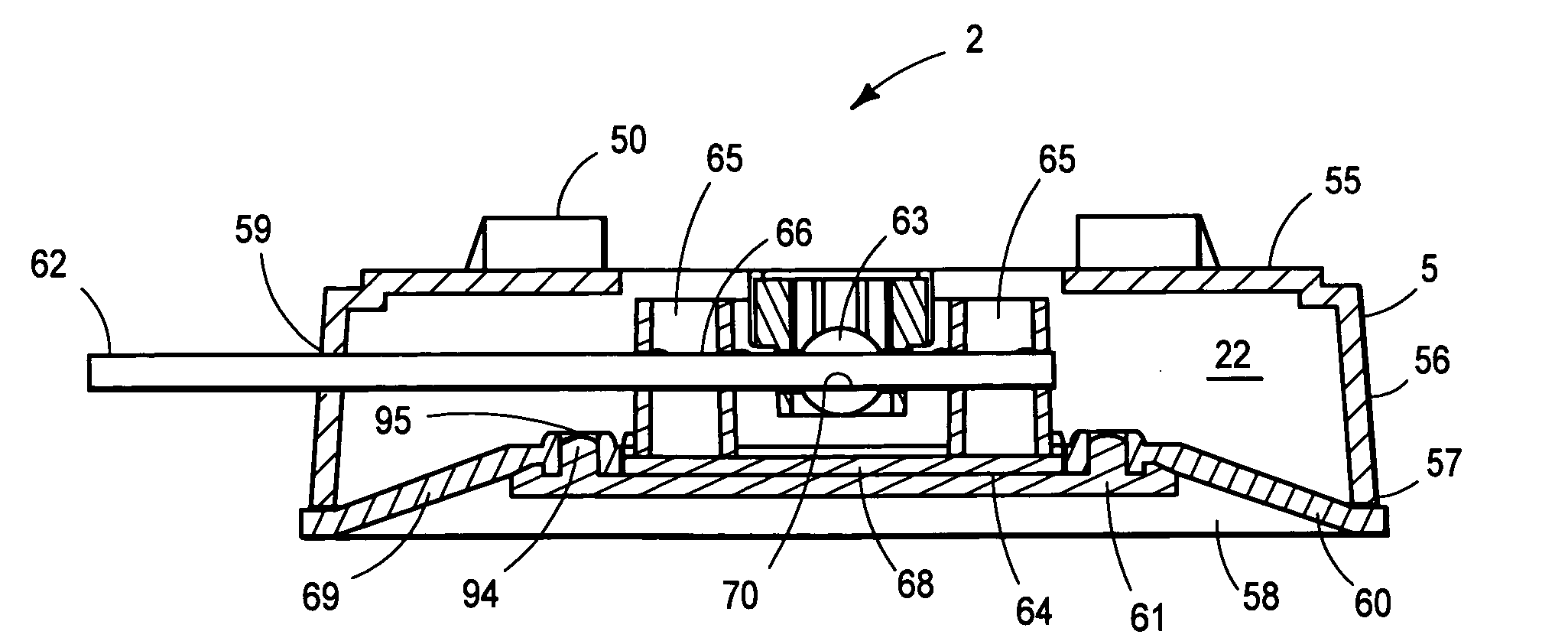
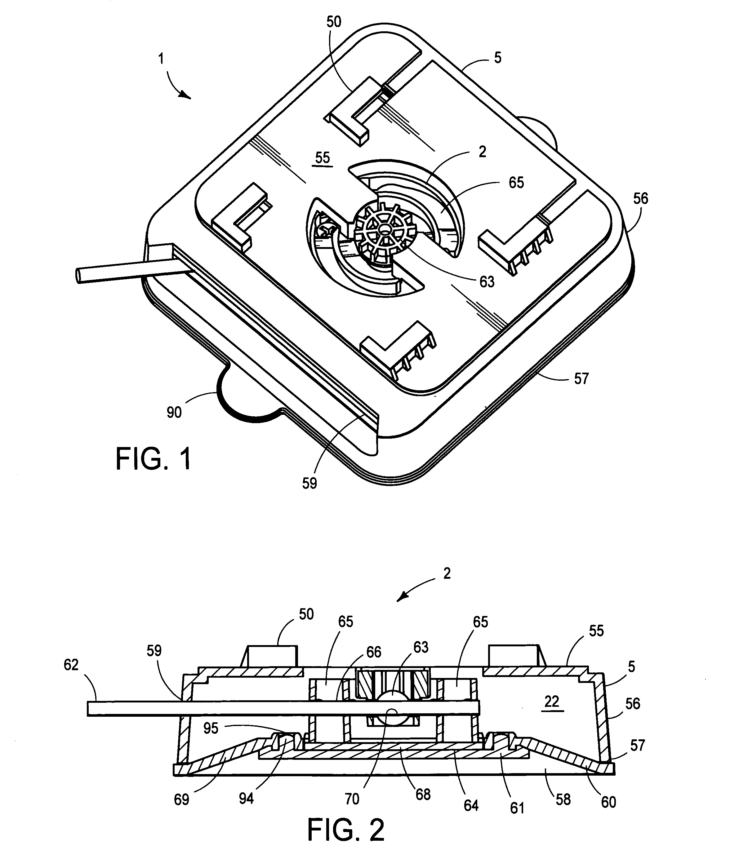
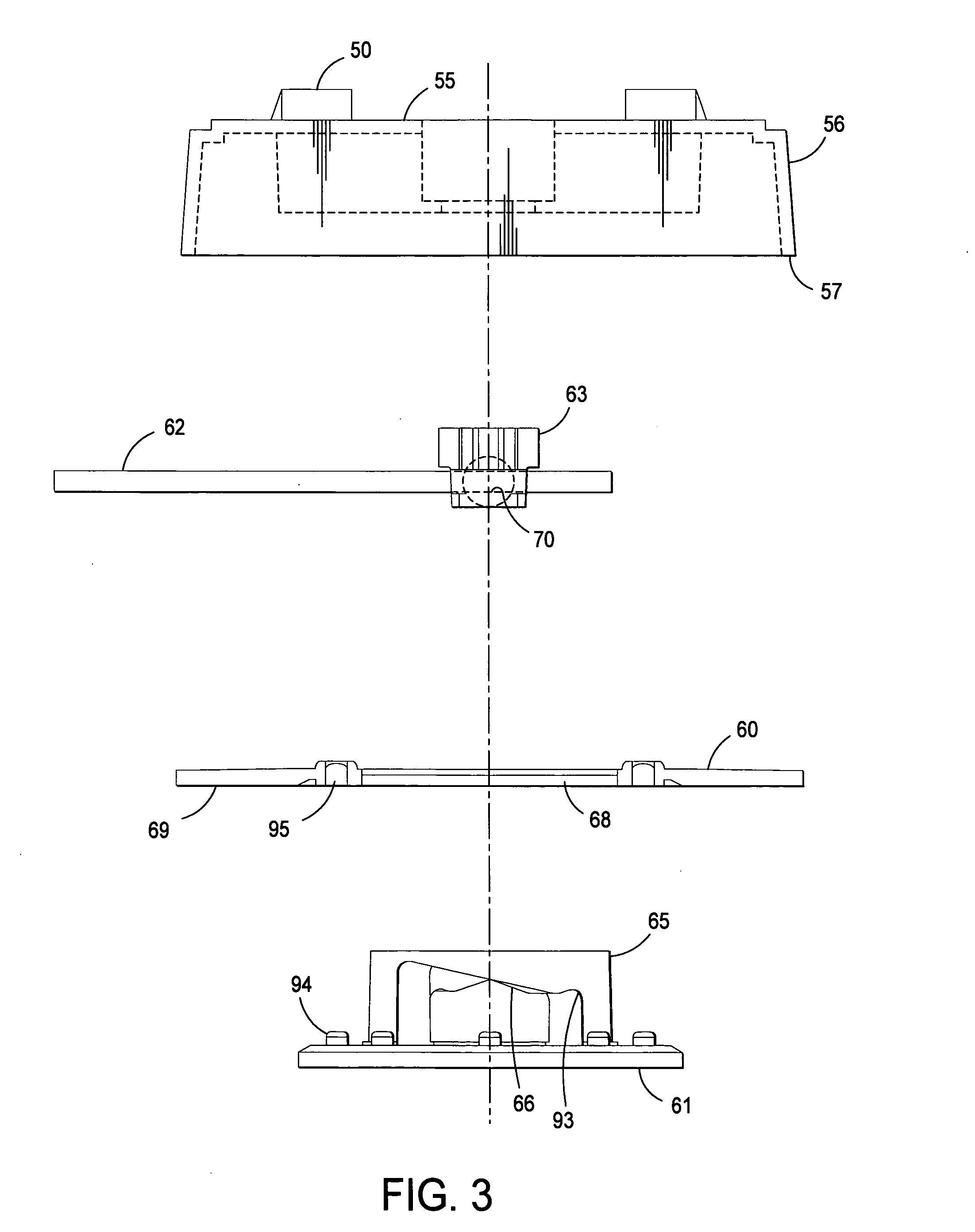
[0047] As shown in FIGS. 1 and 3, a suction device assembly 1 comprises a suction device 2 and a base 5.

Base

[0048] As can be best seen in FIG. 2, the base 5 forms an interior chamber 22 and has an attachment structu...


PUM


Abstract

A suction device that may be configured and conformed to a multitude of different types of kitchenware, small appliances, and other devices. The suction device comprises a base, a handle, a pivot, a plate, and a suction pad. The suction pad is connected to the plate. Two bridge-like structures with sloped undersides extend from the plate. The handle extends from the underside of one of the bridge-like structures, through the pivot, to the underside of the second bridge-like structure, and out through an elongated slot in the base. The handle is in sliding contact with the sloped undersides of the bridge-like structures. As the handle is moved in the elongated slot, the sliding contact of the handle with the undersides of the bridge-like structures pulls the plate, as well as a central portion of the suction pad, away from the surface to which the suction pad is mated, creating a partial vacuum between the central portion of the suction pad and the mating surface and, thus, causing the outer portion of the suction pad to adhere to the surface. Movement of the handle in the opposite direction in the elongated slot causes the plate to move toward the mating surface and, thus, relaxes the suction pad so that the suction pad is no longer adheres to the surface. The base can be configured and constructed in numerous ways and, thus, can be used with a great variety of kitchenware and other items. The base may also be constructed to be removably attached to various kitchenware items and implements.

Description

RELATED APPLICATIONS [0001] This application is a continuation-in-part of U.S. patent application Ser. No. 29 / 232,222, filed Jun. 16, 2005; U.S. patent application Ser. No. 29 / 232,229, filed Jun. 16, 2005; U.S. patent application Ser. No. 29 / 232,215, filed Jun. 16, 2005; U.S. patent application Ser. No. 29 / 232,220, filed Jun. 16, 2005; U.S. patent application Ser. No. 29 / 232,225, filed Jun. 16, 2005; U.S. patent application Ser. No. 29 / 232,321, filed Jun. 16, 2005; U.S. patent application Ser. No. 29 / 232,217, filed Jun. 16, 2005; U.S. patent application Ser. No. 29 / 232,271, filed Jun. 16, 2005; U.S. patent application Ser. No. 29 / 232,218, filed Jun. 16, 2005; U.S. patent application Ser. No. 29 / 232,248, filed Jun. 16, 2005; U.S. patent application Ser. No. 29 / 232,226, filed Jun. 16, 2005; and U.S. patent application Ser. No. 29 / 232,228, filed Jun. 16, 2005. The aforementioned applications are incorporated herein by reference.FIELD OF INVENTION [0002] The field of the invention is me...

Claims


Application Information

Patent Timeline
Patent Type & Authority Applications(United States)
IPC IPC(8): A45D42/14F16B47/00
CPCA47G29/093A47J36/34A47J43/0727F16B47/00A47J43/25A47J47/005A47J47/16A47J43/24
Inventor PARADISE, CHARLES S.HENRY, LOUIS F.
Owner LIFETIME BRANDS
Learn More