Transmission ion microscope

a technology of transmission ion microscope and electron microscope, which is applied in the field of microscopy, can solve the problems of large, complex and expensive instruments utilizing very high energy electrons, operational burden, and slow methods that require mechanically, and achieve the effect of improving contras

Active Publication Date: 2006-12-21
ALIS CORP
View PDF47 Cites 34 Cited by
  • Summary
  • Abstract
  • Description
  • Claims
  • Application Information

AI Technical Summary

Benefits of technology

[0006] Another embodiment further includes a condenser aperture between the electrostatic condenser lens means and the sample to exclude high angle ions. An objective aperture and a selected area aperture between the objective lens and the projector lens may also be provided to restrict the beam. The objective aperture enhances contrast by blocking out high-angle diffracted electrons while the selected area aperture enables a user to examine the periodic diffraction of electrons by ordered arrangements of atoms in the sample. The electrostatic condenser lens means may include first and second condenser lenses. It is also preferred that the ion beam have a sub-nanometer beam diameter.

Problems solved by technology

A TEM is a large, complex and expensive tool utilizing very high energy electrons.
The use of very high energy electrons results in an operational burden.
These are slow methods that require mechanically scanning a very fine needle-shaped tip over a sample.
These methods cannot, however, provide information on what is below the top atomic layer of the sample.
Those skilled in the art will appreciate that existing microscopes lack sufficient contrast capability for a fuller understanding of the microscopic world.

Method used


Image

  • Transmission ion microscope
  • Transmission ion microscope

Examples


Embodiment Construction

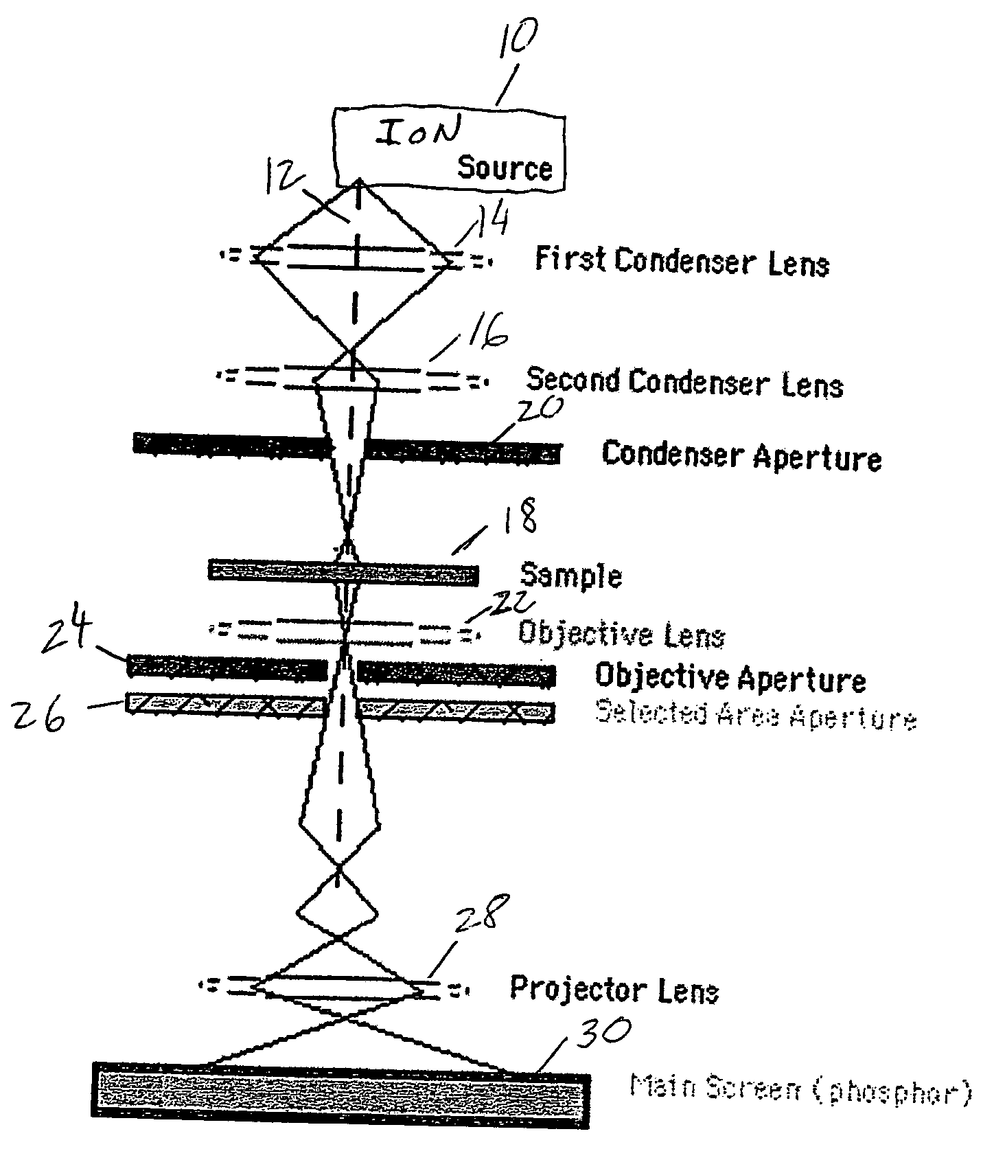
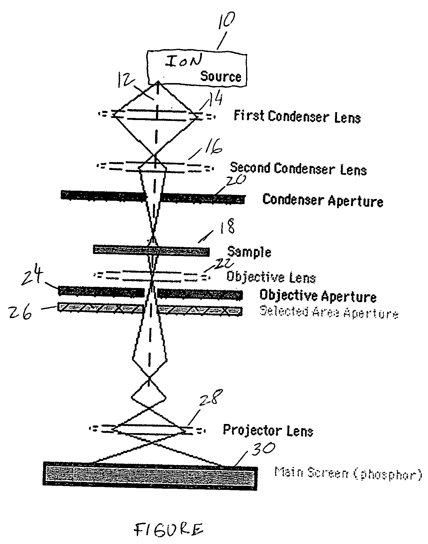
[0008] The transmission ion microscope of the invention works substantially the same way as known transmission electron microscopes (TEM) that can be thought of as an analogy to a slide projector. A slide projector shines a beam of light through a slide and as the light passes through it is affected by the structures and objects on the slide. These effects result in only certain parts of the light beam being transmitted through certain parts of the slide. The transmitted beam is then projected through a viewing screen forming an enlarged image of the slide.

[0009] Existing prior art transmission electron microscopes work the same way as a slide projector except that such microscopes shine a beam of electrons through a specimen rather than light. Whatever part of the electron beam is transmitted is projected onto a phosphor screen for the user to see. In the present invention, the source of ions replaces a source of electrons in a typical TEM.

[0010] With reference to the single FIGU...


PUM


Abstract

Transmission ion microscope. A bright light ion source generates an ion beam that is focused on a sample by an electrostatic condenser lens means. An objective lens focuses the ion beam transmitted through the sample to form an image. A projector lens enlarges the image and a phosphor screen receives the enlarged image to generate light allowing visualization of the image.

Description

BACKGROUND OF THE INVENTION [0001] This invention relates to microscopy and more particularly to a transmission ion microscope using a bright light ion source. [0002] The transmission electron microscope (TEM) has been in use for almost fifty years and has atomic or near atomic resolution. A transmission electron microscope sends a focused beam of electrons through a sample and an image is created on a phosphor screen by transmitted electrons so that atomic structure of the sample can be visualized. A TEM is a large, complex and expensive tool utilizing very high energy electrons. The use of very high energy electrons results in an operational burden. [0003] Atomic level surface structure from thick samples can be obtained by scanning tunneling microscopy (STM) and, to a lesser extent, by atomic force microscopy (AFM). These are slow methods that require mechanically scanning a very fine needle-shaped tip over a sample. These methods cannot, however, provide information on what is b...

Claims


Application Information

Patent Timeline
Patent Type & Authority Applications(United States)
IPC IPC(8): G21K7/00
CPCH01J37/26H01J2237/262H01J2237/0807H01J2237/08
Inventor WARD, BILLY W.
Owner ALIS CORP
Why Eureka
Try Eureka