
Detector assembly

a technology of detectors and components, applied in the field of detectors, can solve the problems of time-consuming and troublesome, and achieve the effect of improving vapour detection

Inactive Publication Date: 2006-12-21
XCOUNTER
View PDF8 Cites 6 Cited by
  • Summary
  • Abstract
  • Description
  • Claims
  • Application Information

AI Technical Summary

Benefits of technology

[0005] An object of the present invention is to provide improved vapour detection, enabling the detection of vapour in a reliable yet simple way, not requiring various steps to be performed.
[0006] A further object of the invention is to provide a detector assembly with increased sensitivity, and also a less expensive detector assembly.

Problems solved by technology

However, to arrange a number of different detector devices in an environment to be supervised, such as a house, is forcing the user to perform maintenance of several devices, for example changing power sources and cleaning the detectors, which is time consuming and troublesome.

Method used


Image

  • Detector assembly
  • Detector assembly
  • Detector assembly

Examples


Embodiment Construction

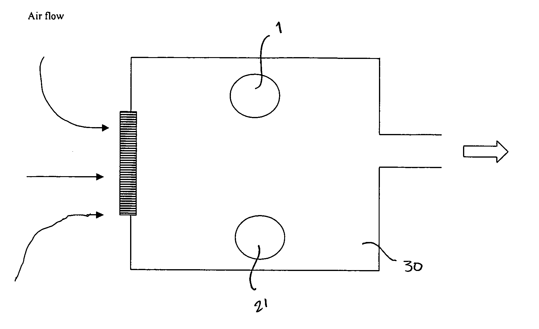
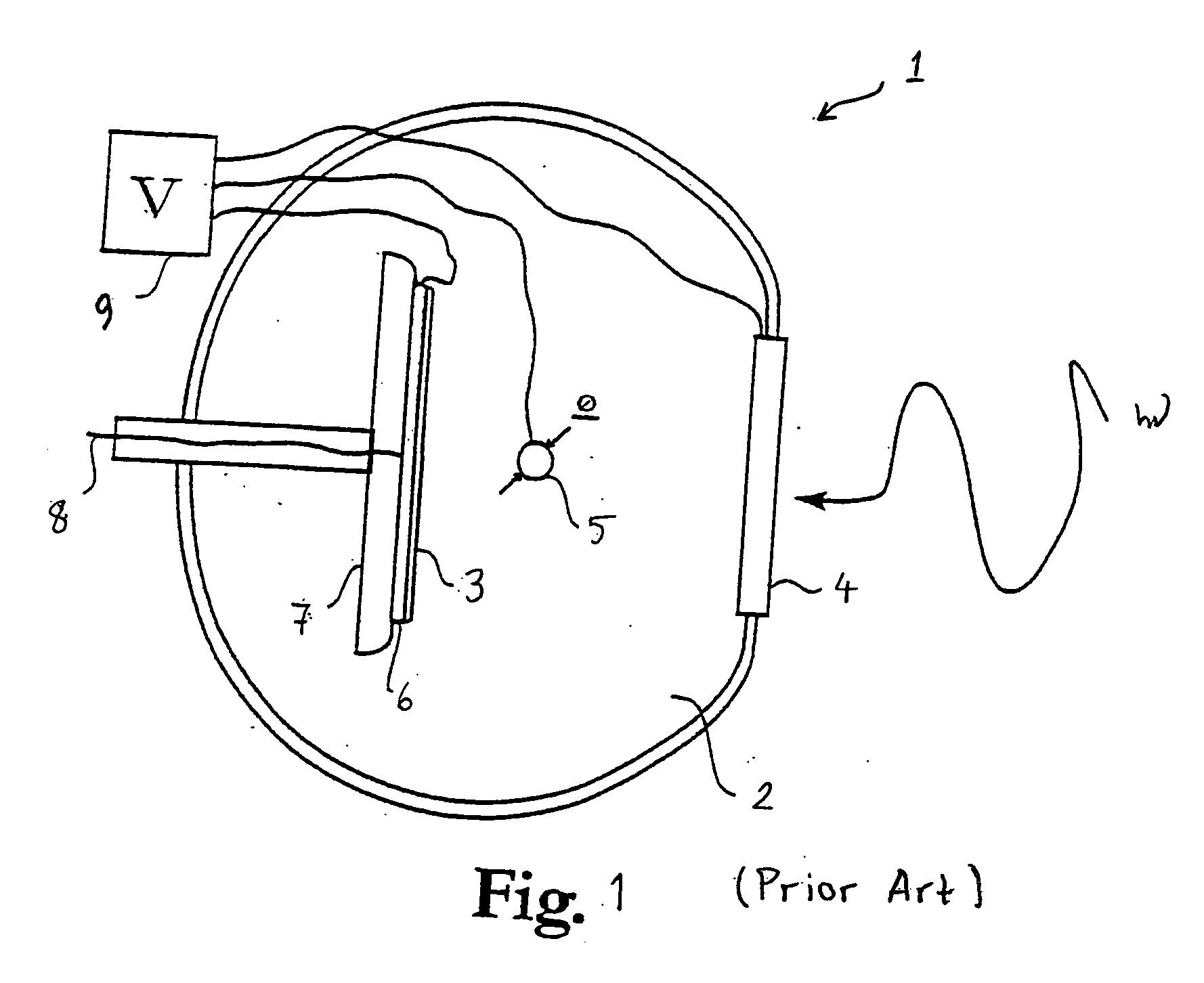
[0037] The present invention is based on a flame detector previously described in the International publication WO 02 / 097757, assigned to the same applicant as the present application. This state of the art flame detector 1 comprises a gas tight detection chamber 2 filled with a gas suitable for electron multiplication. An UV photon sensitive photocathode 3 is placed within the chamber 2 on a UV transparent window 4 in such a way that UV light from a flame can strike the UV sensitive photocathode and be absorbed. Further, an anode in the form of a wire 5 is arranged parallel to the UV sensitive photocathode 3 at a suitable distance. A voltage supply unit 9 is connected to the photocathode 3, the anode wire 5 and to a readout arrangement 6-8 such that an electric field is created between the photocathode 3 and the anode wire 5, whereby a concentrated electric field is created around the anode wire 5. UV photons from a flame hit the photocathode 3 and electrons are thereby released. T...


PUM


Abstract

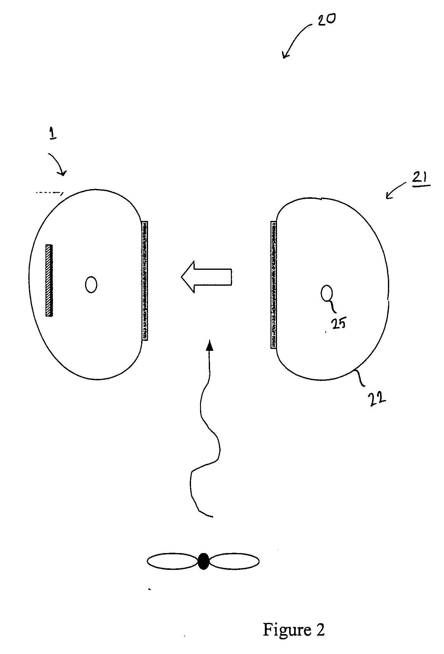
The invention is related to a detector assembly for detecting vapours, smoke and flames, comprising a detector unit 1 having a UV sensitive photocathode 3, an anode 5, a voltage supply unit 9 connected to the UV sensitive photocathode 3 and to the anode 5 to create an electric field such that photoelectrons emitted from the UV sensitive photocathode 3, when struck by UV light, are forced to move towards the anode 5, and a readout arrangement for detecting charges induced by electrons moving towards the anode 5 thereby generating a signal related to the intensity of detected UV light. The detector assembly further comprises an artificial source 21 for emitting radiation having wavelengths within a wavelength interval, the source 21 being oriented such that UV light from the source 21 can strike the UV sensitive photocathode 3. The wavelength interval coincides with a transmission band of air, and with an absorption band of vapours containing molecules of a complex structure. If a decrease of the signal between the detector 1 and the source 21 is detected a presence of a vapour can be established. The invention is also related to such a method.

Description

FIELD OF THE INVENTION [0001] The present invention is related to the field of detectors, and in particular to a detector assembly for detecting vapours as defined in the preamble of claim 1, and a method for detecting vapours as defined in claim 23. BACKGROUND OF THE INVENTION [0002] It is most natural that people want to protect their life and property, and to this end there is an abundance of different kinds of detector devices available. Fire detectors, smoke detectors and gas detectors are examples of such detectors, and they are frequently used in households with the purpose of increasing the safety by giving an as early as possible warning of potential dangers. [0003] Generally, smoke detectors are based on the detection of smoke aerosols by adsorption of smoke particles on atmospheric ions or by detecting optical effects in such smoke aerosols, for example detecting the scattering of optical radiation. There are several drawbacks with such smoke detectors. For example, it is...

Claims


Application Information

Patent Timeline
IPC IPC(8): G01J1/42
CPCG01N21/33G08B25/002G08B17/12G08B17/117
Inventor PESKOV, VLADIMIRFRANCKE, TOM
Owner XCOUNTER
Learn More