Optical unit manufacturing method, optical unit, and forming apparatus

a manufacturing method and optical unit technology, applied in the direction of manufacturing tools, instruments, lenses, etc., can solve the problems of difficult to precisely form the lens contour, high degree of skill, and difficulty in meeting the demand for precise alignment, so as to reduce the degree of formability and high precision in alignment of the optical elemen

Inactive Publication Date: 2006-12-21
SONY CORP
View PDF5 Cites 23 Cited by
  • Summary
  • Abstract
  • Description
  • Claims
  • Application Information

AI Technical Summary

Benefits of technology

[0022] According to the above embodiment of the present invention, the need for manufacturing the optical element of a larger size for centering may be eliminated, resulting in a reduction in degree of formability. Further, the need for performing exact management of a material weight may be also eliminated, unlike the no-centering-required forming. Furthermore, because of no need for a separate process to unite the optical eleme

Problems solved by technology

Further, there are also many types of optical lenses being difficult to locate an optical element axis, like an aspherical lens, leading to a difficulty in also meeting a demand for precise alignment of an optical element with a support frame or a lens barrel for securing the optical element.
However, use of this method causes an error occurring at the time when making alignment involved in installation of the lens on the centering machine to overlap with an error occurring at the time when securing the lens to the lens barrel or a mounting frame.
However, it is quite difficult to precisely form the lens contour at the same t

Method used


Image

  • Optical unit manufacturing method, optical unit, and forming apparatus
  • Optical unit manufacturing method, optical unit, and forming apparatus
  • Optical unit manufacturing method, optical unit, and forming apparatus

Examples


Embodiment Construction

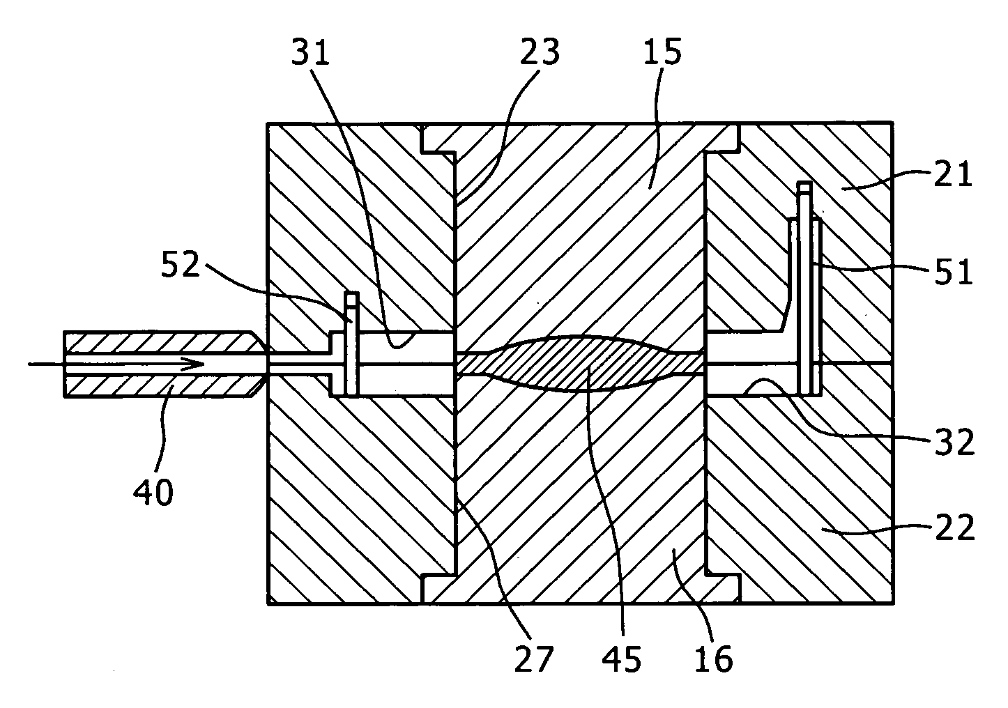
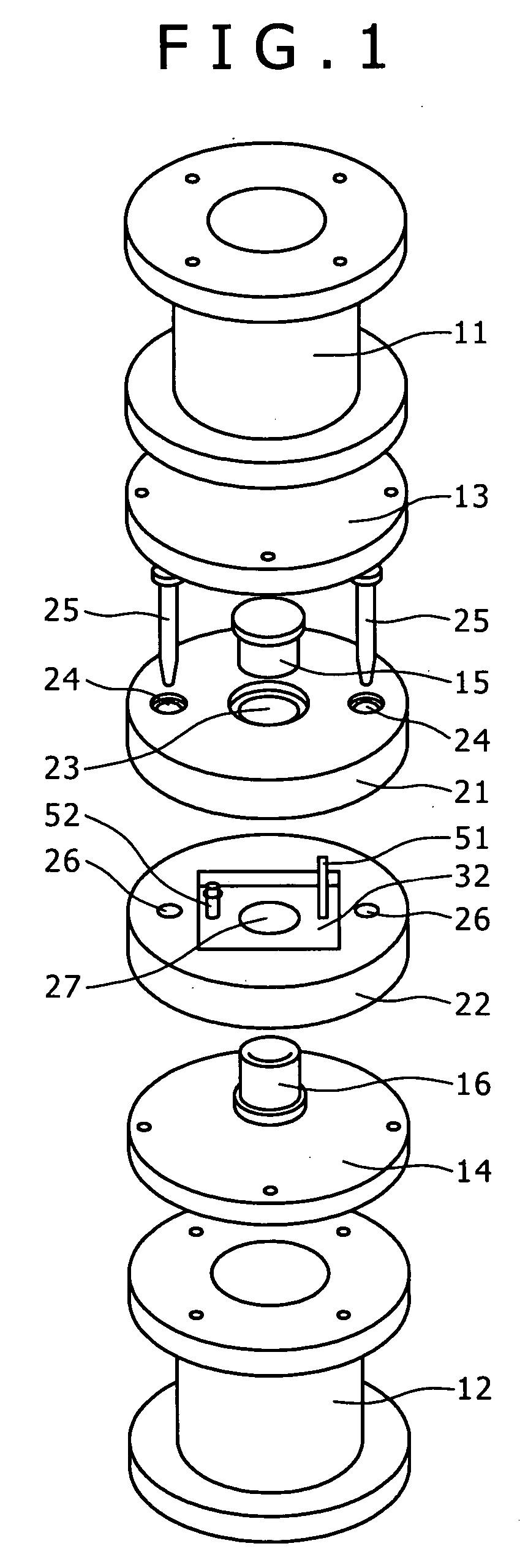
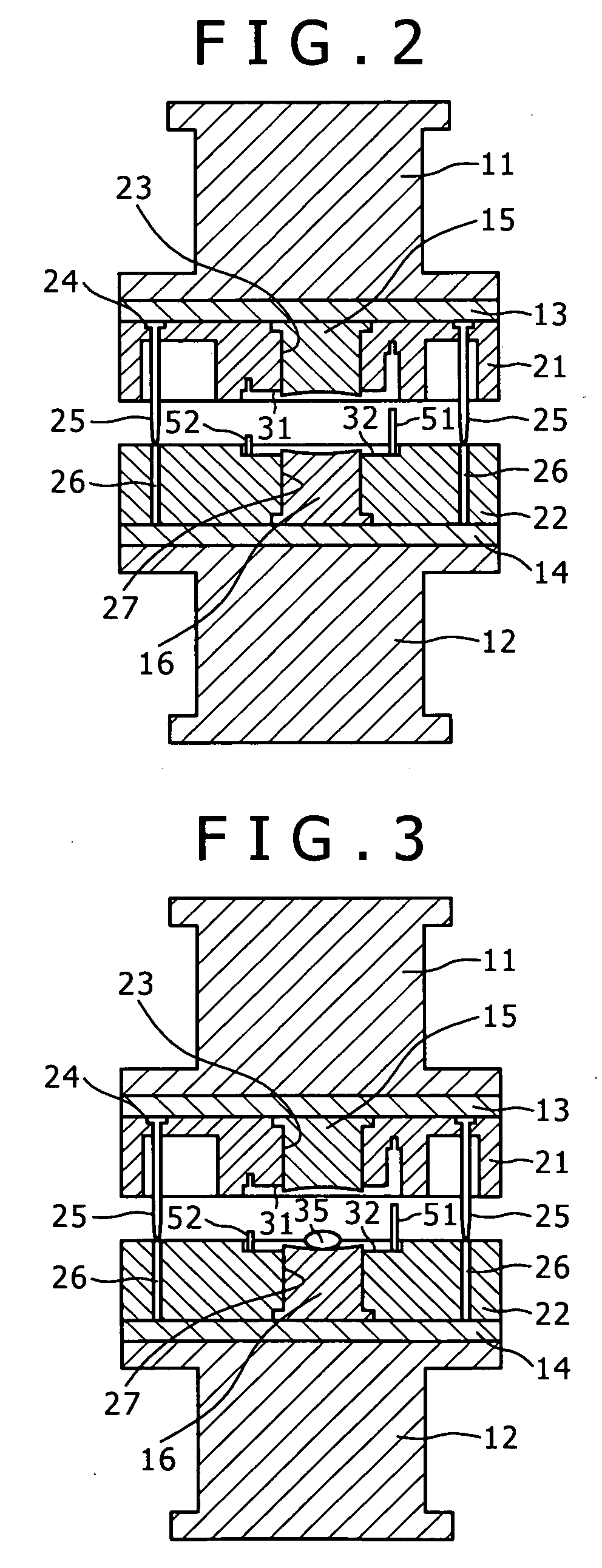
[0031]FIGS. 1 and 2 illustrate a forming apparatus used to manufacture an optical unit according to one embodiment of the present invention, and the illustrated forming apparatus has an upper shaft 11 and a lower shaft 12. A lower surface of the upper shaft 11 is fitted with a die plate 13, and an upper surface of the lower shaft 12 is fitted with a die plate 14. Then, these die plates 13 and 14 are adaptable to hold a top part 15 and a bottom part 16 respectively.

[0032] The top part 15 and the bottom part 16 both contained in a mold are configured to be held with upper and lower drum parts 21 and 22. The upper drum part 21 has a circular center hole 23 in the center thereof, permitting the top part 15 to be secured after being fitted into the center hole 23. The upper drum part 21 also has a pair of insertion holes 24 located in a symmetrical configuration around the center hole 23. A pair of locating pins 25 planted on a lower surface of the upper die plate 13 may be respectively...


PUM

PropertyMeasurementUnit
Temperatureaaaaaaaaaa
Pressureaaaaaaaaaa
Angleaaaaaaaaaa

Abstract

There is provided an optical unit manufacturing method in which an optical element is obtained by giving compression to an optical material using a mold after thermal softening of the optical material, and uniting of a frame unit with the optical element is required. The optical unit manufacturing method includes a step of forming the frame unit as an integral part of the optical element with reference to a position of the mold while holding the optical element without opening the mold after forming of the optical element.

Description

CROSS REFERENCES TO RELATED APPLICATIONS [0001] The present document contains subject matter related to Japanese Patent Application JP 2005-177024 filed in the Japanese Patent Office on Jun. 16, 2005, the entire contents of which being incorporated herein by reference. BACKGROUND OF THE INVENTION [0002] 1. Field of the Invention [0003] The present invention relates to an optical unit manufacturing method, an optical unit, and a mold thereof. More particularly, the present invention relates to an optical unit manufacturing method in which an optical element united with a frame unit is obtained by performing compression (press forming) to an optical material with a mold after thermal softening of the optical material, an optical unit resulting from use of the above method, and a forming apparatus used to form the above optical unit. [0004] 2. Description of Related Arts: [0005] A small-sized high-performance optical lens is used as an optical system of an electronic image capturing me...

Claims


Application Information

Patent Timeline
IPC IPC(8): B29D11/00
CPCB29C43/00B29C43/021B29C43/14B29C45/16B29C2043/3618G02B7/10B29L2012/00C03B11/08C03B2215/60C03B2215/79B29L2011/0016
Inventor YAMAMICHI, NOBUHIRO
Owner SONY CORP
Why Eureka
Try Eureka