Organic electroluminescent device

a technology of electroluminescent devices and organic materials, which is applied in the direction of discharge tube luminescnet screens, natural mineral layered products, other domestic articles, etc., can solve the problems of reducing process yield, color shift due to life difference, and hard mask-making, and achieves high quantum efficiency, superior carrier transport ability, and the effect of improving the yield

Active Publication Date: 2006-12-21
AU OPTRONICS CORP
View PDF7 Cites 9 Cited by
  • Summary
  • Abstract
  • Description
  • Claims
  • Application Information

AI Technical Summary

Benefits of technology

[0013] In one aspect of the present invention, an organic electroluminescent device is provided to at least comprise a first electrode, an organic color conversion layer, a carrier transporting layer, an emissive layer, and a second electrode. The organic color conversion layer is disposed on the first electrode. The carrier transporting layer is disposed on the organic color conversion layer. The emissive layer is disposed on the carrier transporting layer. The second electrode is disposed on the emissive layer. The organic color conversion layer has the superior carrier transporting ability and high quantum efficiency. Besides color conversion, the organic color conversion layer can provide these carriers with injecting. The carrier transporting layer is disposed between the organic color conversion layer and the emissive layer. Thus, the carriers from the second electrode do not go into the organic color conversion layer by way of the emissive layer.
[0014] Due to the only one emissive layer, the manufacturing process in the white OELD of the present invention is easier than the conventional white OELD. In addition, the red, green, and blue light is defined as the color filters, not generated from the color conversion. Therefore, in the stage of fabricating OELD, it is unnecessary to add an isolating structure, like ITO, SiNx, SiOx etc., between these color conversion layers for preventing the color shift due to color light mixing.

Problems solved by technology

But a disadvantage is, after a long term use, a color shift occurs due to the difference in life between the emissive layers 11, 12, 13.
In addition, reduction in pixel size may result in harder mask-making so as to reduce the process yield.
However, it is difficult to produce the white OELD 15 that can emit “pure” white light.
A disadvantage is, the distribution of the excitons is easy to change with the electrical field, so the color shift is made possible.
However, the disadvantage is the emergent light of each pixel of the organic electroluminescent display 10c may scatter to mix with different color light of other pixel, so as to cause a color shift.
In this way, the light need to be filtered twice, so the luminance and the efficiency reduce significantly.
As usually, the CCM is hard to develop due to the requirement of high color purity and high efficiency, so the full-color OELD technology according to the CCM is rarely used in the industrial circle.

Method used


Image

  • Organic electroluminescent device
  • Organic electroluminescent device
  • Organic electroluminescent device

Examples


Embodiment Construction

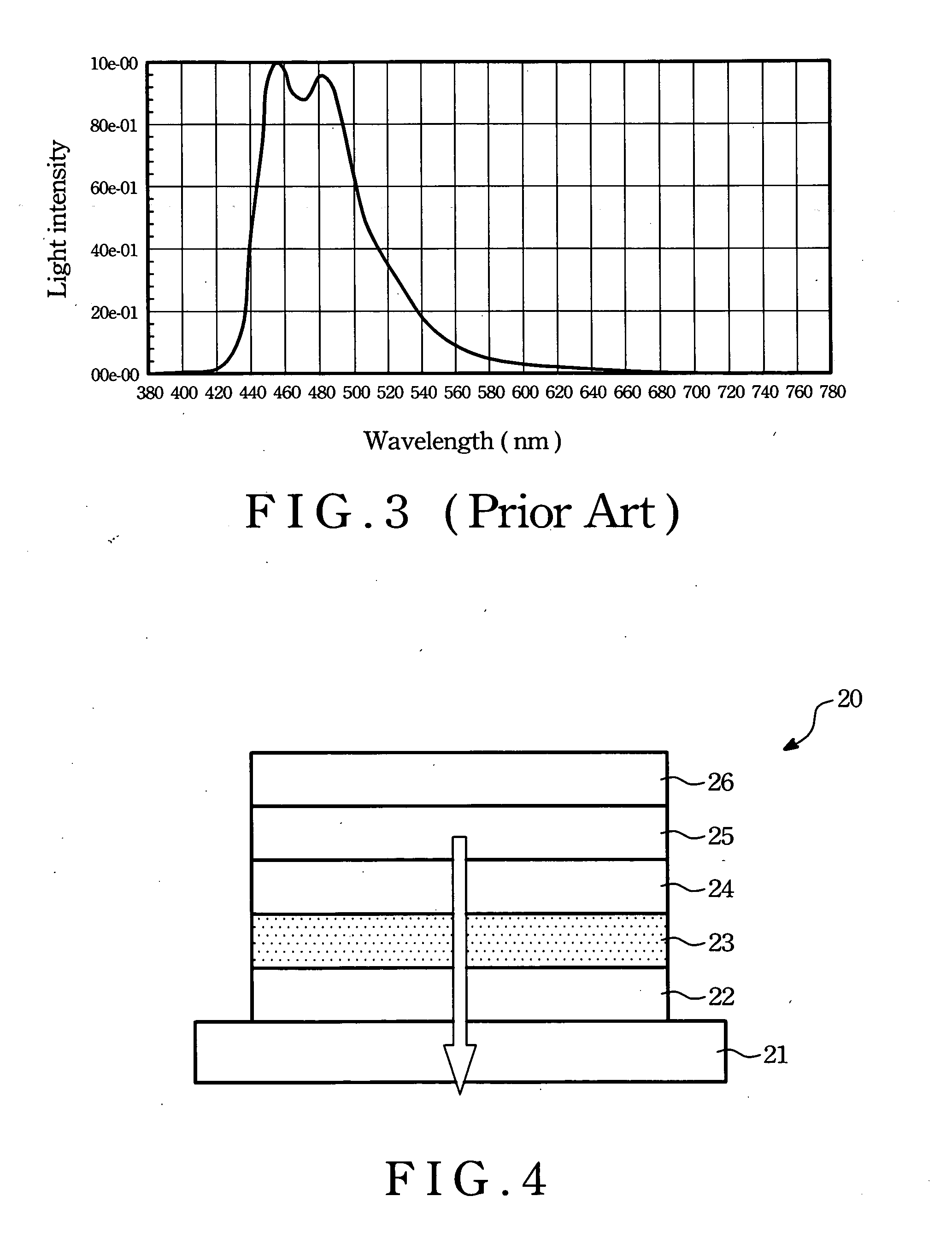
[0030] Referring to FIG. 4, an organic electroluminescent device (OELD) 20, at least comprises a first electrode 22, an organic color conversion layer 23, a carrier transporting layer 24, an emissive layer 25, and a second electrode 26. The organic color conversion layer 23 is disposed on the first electrode 22. The carrier transporting layer 24 is disposed on the organic color conversion layer 23. The emissive layer 25 is disposed on the carrier transporting layer 24. The second electrode 26 is disposed on the emissive layer 25. The organic color conversion layer 23 has the superior carrier transporting ability and high quantum efficiency. Besides the function of color conversion, the organic color conversion layer 23 at the same time as a carrier injection layer can be provide these carries with injection function. In order to achieve the goal of light emitting, the organic color conversion layer 23 allows only one kind of carrier through itself, for example, one of the electrons ...


PUM

PropertyMeasurementUnit
thicknessaaaaaaaaaa
wavelengthaaaaaaaaaa
HOMOaaaaaaaaaa

Abstract

An organic electroluminescent device comprises a fist electrode, an organic color conversion layer, a carrier transport layer, an emissive layer, and a second electrode. The organic color conversion layer is disposed over the first electrode. The carrier transport layer is disposed over the organic color conversion layer. The emissive layer is disposed over the carrier transport layer. The second electrode is disposed over the emissive layer.

Description

[0001] This application claims the benefit of Taiwan Application Serial No. 094120665, filed Jun. 21, 2005, the subject matter of which is incorporated herein by reference. BACKGROUND OF THE INVENTION [0002] (1) Field of the Invention [0003] The present invention relates to an organic electroluminescent device, and more particularly, to an organic electroluminescent device having a color conversion layer. [0004] (2) Description of the Prior Art [0005] In present, the full-color technology used in an organic electroluminescent display is classified into three types: (1) red, green, and blue light sources placed side-by-side pattern, (2) white light source through each of red, green, and blue color filters, and (3) color change media (CCM) replacing the color filters to convert blue light into other color lights. A brief introduction follows. [0006]FIG. 1A shows an organic electroluminescent display 10a fabricated by placing red, green, and blue sub-pixels side-by-side pattern. As sho...

Claims


Application Information

Patent Timeline
Patent Type & Authority Applications(United States)
IPC IPC(8): H01L51/52
CPCH01L27/3211H01L51/5206H01L27/322Y10S428/917H10K59/35H10K59/38H10K50/81
Inventor LEE, CHUNG-CHUN
Owner AU OPTRONICS CORP
Why Eureka
Try Eureka