
Delay-Locked Loop Device Capable Of Anti-False-Locking And Related Methods

a loop device and delay-locked technology, applied in the direction of electrical equipment, pulse automatic control, etc., can solve problems such as delay, and achieve the effect of simplifying the delay-locked loop devi

Active Publication Date: 2006-12-21
FARADAY TECH CORP
View PDF5 Cites 7 Cited by
  • Summary
  • Abstract
  • Description
  • Claims
  • Application Information

AI Technical Summary

Benefits of technology

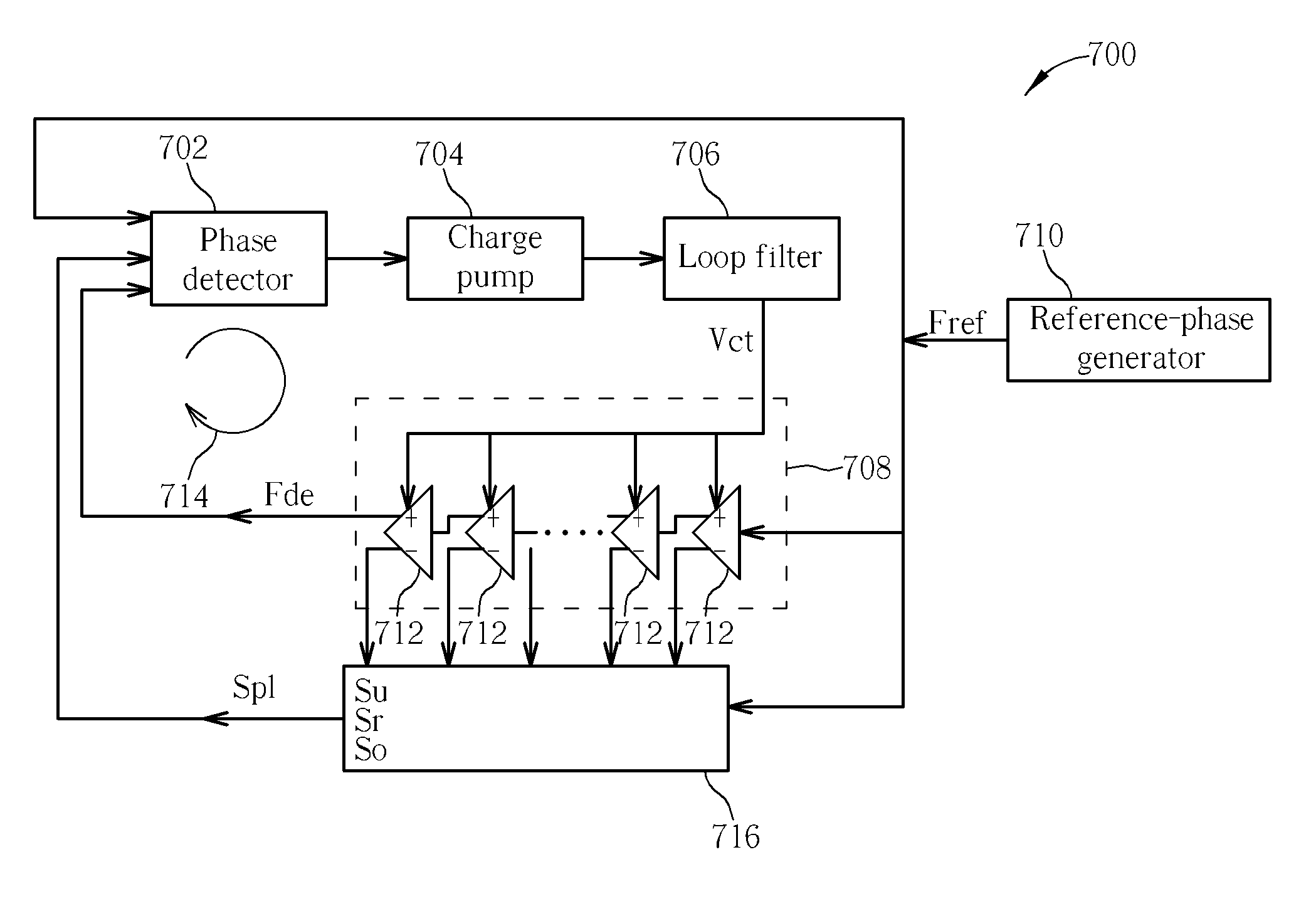
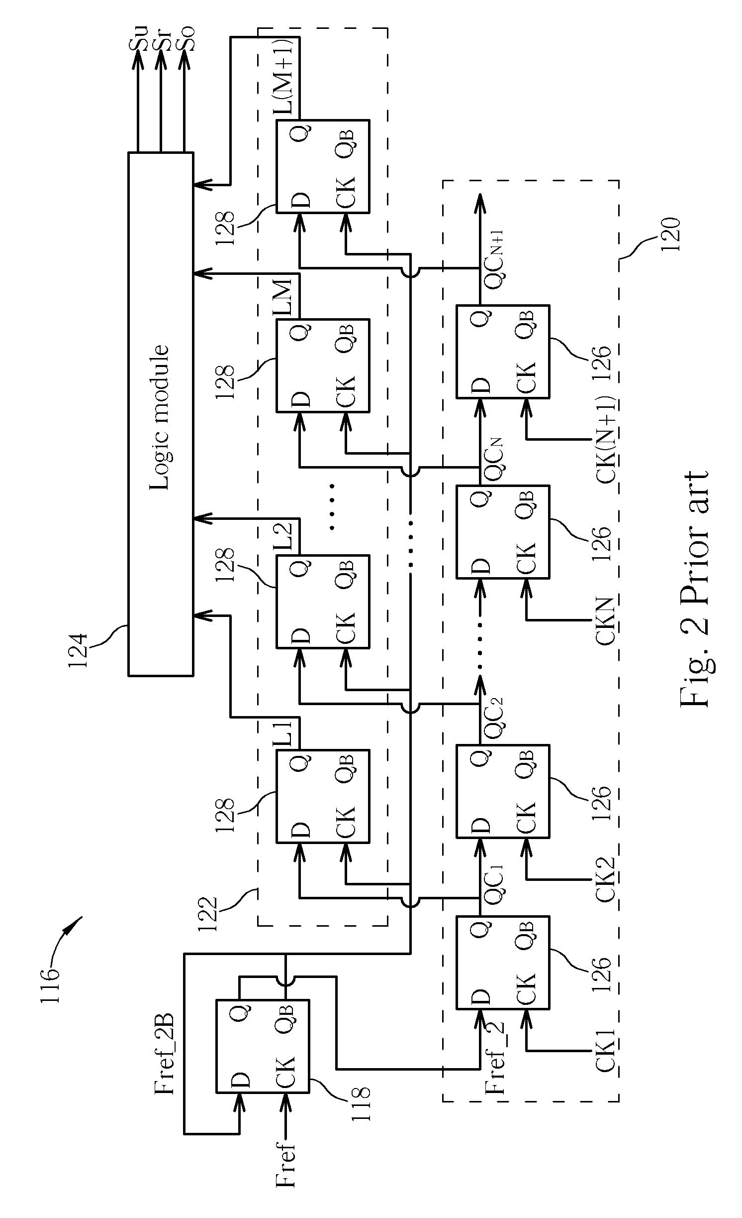
[0010] The present invention discloses a method for simplifying a delay-locked loop device. First of all, phases outputted from delay units of a voltage control delay circuit in the delay-locked loop device are reversed. Then, the reversed phases are transmitted to shift registers in a first shift register set corresponding to the delay units of the voltage control delay circuit, so as to generate a first sequence of comparison signals according to a first divided phase and inverse phases of phases outputted from the delay units of the voltage control delay circuit. Next, a plurality of shift registers in the first shift register set corresponding to a plurality of delay units of initial stages of the voltage control delay circuit are removed according to a default requirement. Finally, shift registers in a second shift register set corresponding to the removed shift registers in the first shift register set are removed, so as to generate a second sequence of comparison signals according to a second divided phase and the first sequence of the comparison signals.
[0011] The present invention further discloses a method for performing a delay lock. The method includes following steps. First, the method generates a delayed phase with a voltage control delay circuit according to a reference phase and a control voltage. Second, the method generates a control signal according to a lock indication signal, the reference phase, and the delayed phase with a phase detector. Third, the method transmits the control voltage to the voltage control delay circuit according to the control signal with a charge pump. Fourth, the method generates the lock indication signal for the phase detector according to output phases of at least one delay unit of the voltage control delay circuit with a lock detector. Fifth, the method generates a first sequence of comparison signals according to a first divided phase and the output phases of at least one delay unit of the voltage control delay circuit with a first shift register set. S...

Problems solved by technology

First, the method generates a delayed phase with a voltage control delay circuit according to a reference phase and a control voltage.
Third, the method transmits the control voltage to the voltage control delay circuit according to the control signal with a charge pump.

Method used


Image

  • Delay-Locked Loop Device Capable Of Anti-False-Locking And Related Methods
  • Delay-Locked Loop Device Capable Of Anti-False-Locking And Related Methods
  • Delay-Locked Loop Device Capable Of Anti-False-Locking And Related Methods

Examples


Embodiment Construction

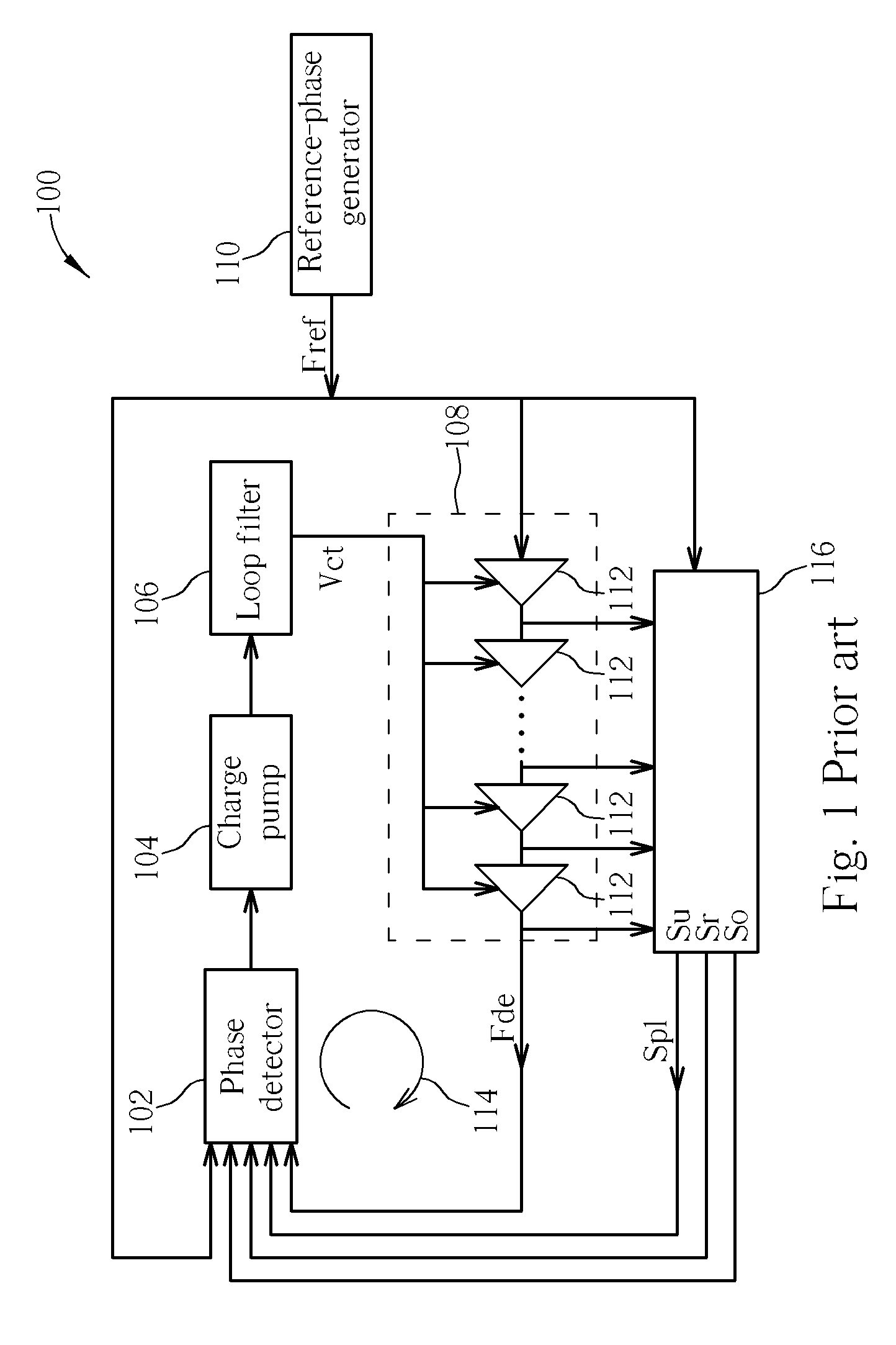
[0025] Please refer to FIG. 6, which illustrates a flowchart of a process 600 for simplifying a DLL device in accordance with the present invention. The process 600 is utilized for simplifying DLL devices such as the DLL device 100 shown in FIG. 1, and includes the following steps:

[0026] Step 602: start.

[0027] Step 604: reverse phases outputted from delay units of a voltage control delay circuit.

[0028] Step 606: transmit the reversed phases in step 604 to shift registers in a first shift register set corresponding to the delay units of the voltage control delay circuit, so as to generate a first sequence of comparison signals according to a first divided phase and inverse phases of phases outputted from the delay units of the voltage control delay circuit;

[0029] Step 608: remove a plurality of shift registers in the first shift register set corresponding to a plurality of delay units of initial stages of the voltage control delay circuit according to a default requirement;

[0030...


PUM


Abstract

The present invention discloses a delay-locked loop device capable of anti-false-locking, which comprises: a voltage control delay circuit comprising a plurality of delay units in a series for generating a delayed phase according to a reference phase and a control voltage; a phase detector coupled to the voltage control delay circuit for generating a control signal according to a lock indication signal, the reference phase, and the delayed phase; a charge pump coupled to the phase detector for transmitting the control voltage to the voltage control delay circuit according to the control signal; and a lock detector coupled to the voltage control delay circuit for generating the lock indication signal for the phase detector according to output phases of at least one delay unit of the voltage control delay circuit.

Description

BACKGROUND OF THE INVENTION [0001] 1. Field of the Invention [0002] The present invention provides a delay-locked loop device capable of anti-false-locking and related methods, and more particularly, a delay-locked loop device capable of decreasing the number of shift registers needed. [0003] 2. Description of the Prior Art [0004] Digital integrated circuits have been highly developed. Personal computers, mobile phones, digital watches, and calculators, for example, are applications of digital integrated circuits. With high-speed, microminiaturized, and multi-function developments, a complex digital integrated circuit often includes a plurality of units. The units delay a reference timer with different degrees, so a delay-locked loop (DLL) device is need for maintaining synchronization of the digital integrated circuit. In order to improve effects of stuck lock, harmonic lock, small lock range and asymmetric duty cycle, the prior art provides a delay-locked loop device capable of an...

Claims


Application Information

Patent Timeline
IPC IPC(8): H03L7/06
CPCH03L7/095H03L7/0812
Inventor YU, MING-SHIHHAN, SONG-RONG
Owner FARADAY TECH CORP
Learn More