Apparatus and methods for haptic rendering using a haptic camera view

a camera view and haptic rendering technology, applied in the field of haptic rendering of virtual environments, can solve the problems of haptic rendering process generally computation-intensive, 3d graphics applications are incompatible with haptic systems, and haptic rendering of 3d objects in virtual environments is a relatively inefficient process

Inactive Publication Date: 2006-12-21
3D SYST INC
View PDF60 Cites 17 Cited by
  • Summary
  • Abstract
  • Description
  • Claims
  • Application Information

AI Technical Summary

Benefits of technology

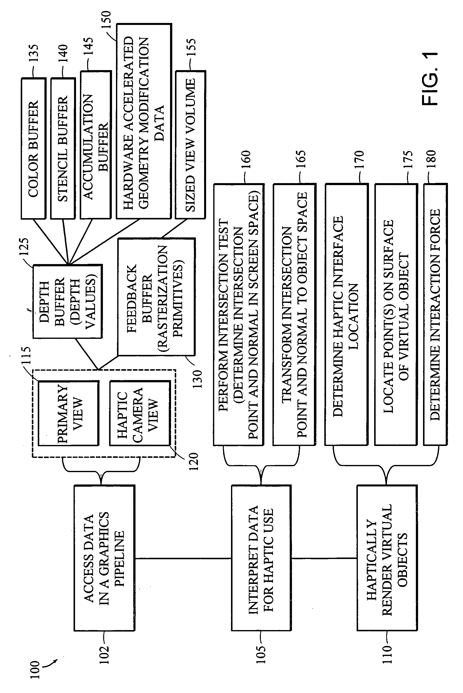
[0011] The efficiency of haptic rendering is improved, because the view volume can be limited to a region of the virtual environment that the user will be able to touch at any given time, and further, because the method takes advantage of the processing capacity of the graphics pipeline. This method also allows haptic rendering of portions of a virtual environment that cannot be seen in a 2D display of the virtual object, for example, the back side of an object, the inside of crevices and tunnels, and portions of objects that lie behind other objects.
[0012] A moving haptic camera offers this advantage. Graphical data from a static camera view of a virtual environment can be used for haptic rendering; however, it is generally true that only geometry visible in the view direction of the camera can be used to produce touch feedback. A moving camera (and / or multiple cameras) allows graphical data to be obtained from more than one view direction, thereby allowing the production of force feedback corresponding to portions of the virtual environment that are not visible from a single static view. The interaction between the user and the virtual environment is further enhanced by providing the user with a main view of the virtual environment on a 2D display while, at the same time, providing the user with haptic feedback corresponding to the 3D virtual environment. The haptic feedback is updated according to the user's manipulation of a haptic interface device, allowing the user to “feel” the virtual object at any position, including regions that are not visible on the 2D display.
[0013] The invention provides increased haptic rendering efficiency, permitting greater haptic processing speeds for more realistic touch-based simulation. For example, in one embodiment, the force feedback computation speed is increased from a rate of about 1000 Hz to a rate of about 10,000 Hz or more. Furthermore, the invention allows more sophisticated haptic interaction techniques to be used with widely-available desktop computers and workstations. For example, forces can be computed based on the interaction of one or more points, lines, planes, and / or spheres with virtual objects in the virtual environment, not just based on single point interaction. More sophisticated haptic interface devices that require multi-point interaction can be used, including pinch devices, multi-finger devices, and gloves, thereby enhancing the user's haptic experience. Supported devices include kinesthetic and / or tactile feedback devices. For example, in one embodiment, a user receives tactile feedback when in contact with the surface of a virtual object such that the user can sense the texture of the surface.
[0018] In one embodiment, a view volume associated with the first virtual camera is sized to exclude geometric elements that lie beyond a desired distance from the haptic interface location. This involves culling the graphical data to remove geometric primitives that lie outside the view volume of the first virtual camera. In one embodiment, hardware culling is employed, where primitives are culled by graphics hardware (i.e. a graphics card). In another embodiment, culling involves the use of a spatial partition, for example, an octree, BSP tree, or other hierarchical data structure, to exclude graphical data outside the view volume. Both hardware culling and a spatial partition can be used together. For example, where the number of primitives being culled by the graphics hardware is large, the spatial partition can reduce the amount of data sent to the hardware for culling, allowing for a more efficient process.
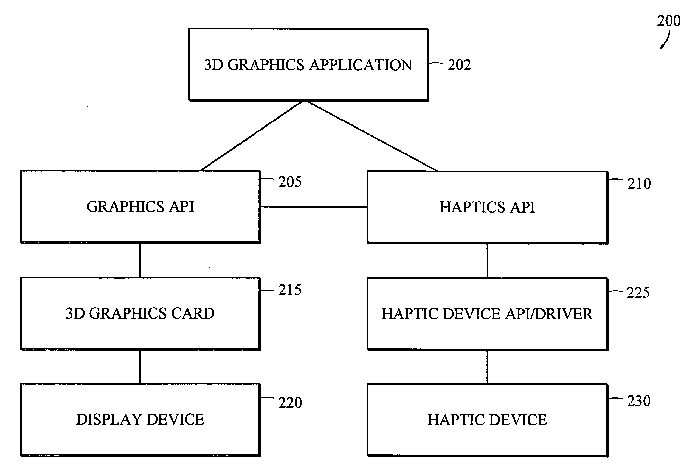
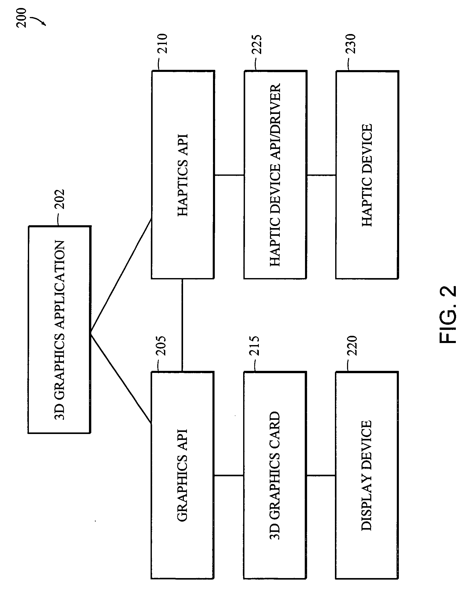
[0026] There may be any number of cameras in a given scene. For example, each individual virtual object in a scene may have its own camera; thus, the number of cameras is unlimited. This allows a user to adapt the camera view to best suit individual objects, which allows for further optimization. For example, the camera position and view frustum for objects that are graphically rendered (and / or haptically rendered) using the depth buffer can be set differently than those rendered using the feedback buffer. In addition, there can be multiple haptic devices in a given scene. Each haptic device can have a different camera for each object, since the position and motion of the haptic devices will generally be different.

Problems solved by technology

While 3D graphics API's and graphics cards have significantly improved the graphical rendering of 3D objects, the haptic rendering of 3D objects in a virtual environment is a comparatively inefficient process.
Haptic rendering is largely a separate process from graphical rendering, and currently-available 3D graphics applications are incompatible with haptic systems, since graphics applications are not designed to interpret or provide haptic information about a virtual environment.
Furthermore, haptic rendering processes are generally computation-intensive, requiring high processing speed and a low latency control loop for accurate force feedback rendering.
For this reason, current haptic systems are usually limited to generating force feedback based on single point interaction with a virtual environment.

Method used


Image

  • Apparatus and methods for haptic rendering using a haptic camera view
  • Apparatus and methods for haptic rendering using a haptic camera view
  • Apparatus and methods for haptic rendering using a haptic camera view

Examples


Embodiment Construction

[0043] Throughout the description, where an apparatus is described as having, including, or comprising specific components, or where systems, processes, and methods are described as having, including, or comprising specific steps, it is contemplated that, additionally, there are apparati of the present invention that consist essentially of, or consist of, the recited components, and that there are systems, processes, and methods of the present invention that consist essentially of, or consist of, the recited steps.

[0044] It should be understood that the order of steps or order for performing certain actions is immaterial so long as the invention remains operable. Moreover, two or more steps or actions may be conducted simultaneously.

[0045] A computer hardware apparatus may be used in carrying out any of the methods described herein. The apparatus may include, for example, a general purpose computer, an embedded computer, a laptop or desktop computer, or any other type of computer ...


PUM


Abstract

The invention provides systems and methods for using a “haptic camera” within a virtual environment and for using graphical data from the haptic camera to produce touch feedback. The haptic camera obtains graphical data pertaining to virtual objects within the vicinity and along the trajectory of a user-controlled haptic interface device. The graphical data from the camera is interpreted haptically, thereby allowing touch feedback corresponding to the virtual environment to be provided to the user.

Description

RELATED APPLICATIONS [0001] The present application is related to commonly-owned U.S. patent application entitled, “Apparatus and Methods for Haptic Rendering Using Data in a Graphics Pipeline,” by Itkowitz, Shih, Midura, Handley, and Goodwin, filed under Attorney Docket No. SNS-012 on even date herewith, the text of which is hereby incorporated by reference in its entirety; the present application is also related to commonly-owned international (PCT) patent application entitled, “Apparatus and Methods for Haptic Rendering Using Data in a Graphics Pipeline,” by Itkowitz, Shih, Midura, Handley, and Goodwin, filed under Attorney Docket No. SNS-012PC on even date herewith, the text of which is hereby incorporated by reference in its entirety; the present application claims the benefit of U.S. Provisional Patent Application No. 60 / 584,001, filed on Jun. 29, 2004, the entirety of which is incorporated by reference herein.FIELD OF THE INVENTION [0002] The invention relates generally to ha...

Claims


Application Information

Patent Timeline
Patent Type & Authority Applications(United States)
IPC IPC(8): G09G5/00G06F3/00G06T15/00
CPCG06F3/016G06F2203/012G06T15/00G06T2215/06G06T15/20G06T15/80G06T19/006G06T19/00G06T2210/28
Inventor ITKOWITZ, BRANDON D.SHIH, LOREN C.MIDURA, MARC DOUGLASSHANDLEY, JOSHUA E.GOODWIN, WILLIAM ALEXANDER
Owner 3D SYST INC
Why Eureka
Try Eureka