Optical scanning device and image forming apparatus

a scanning device and image forming technology, applied in the direction of recording devices, inking devices, instruments, etc., can solve the problem that the adjustment can only be performed for a beam wais

Inactive Publication Date: 2006-12-21
RICOH KK
View PDF23 Cites 83 Cited by
  • Summary
  • Abstract
  • Description
  • Claims
  • Application Information

AI Technical Summary

Problems solved by technology

According to the approach described in Japanese Patent Application Laid-Open No. 2002-365570, since adjustment can be performed in only one direction (the optical axis direction), there is a problem that adjustment can be performed only for a beam waist position (beam spot position adjustment).

Method used


Image

  • Optical scanning device and image forming apparatus
  • Optical scanning device and image forming apparatus
  • Optical scanning device and image forming apparatus

Examples


Embodiment Construction

[0023] Exemplary embodiments of the present invention will be explained in detail below with reference to the accompanying drawings.

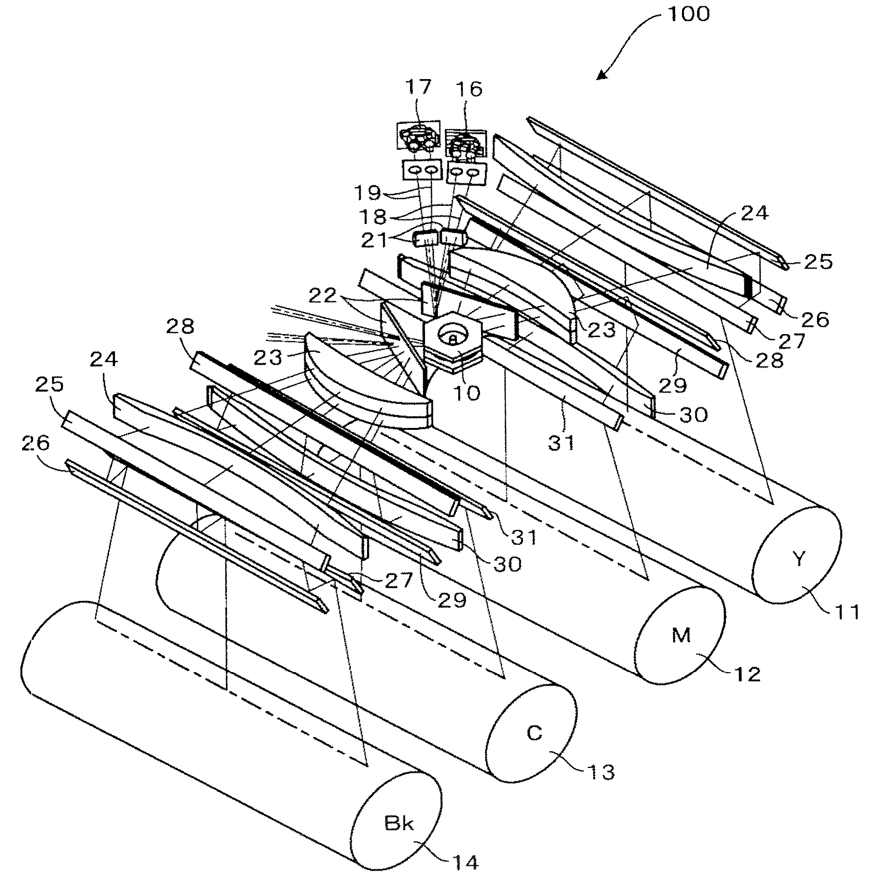
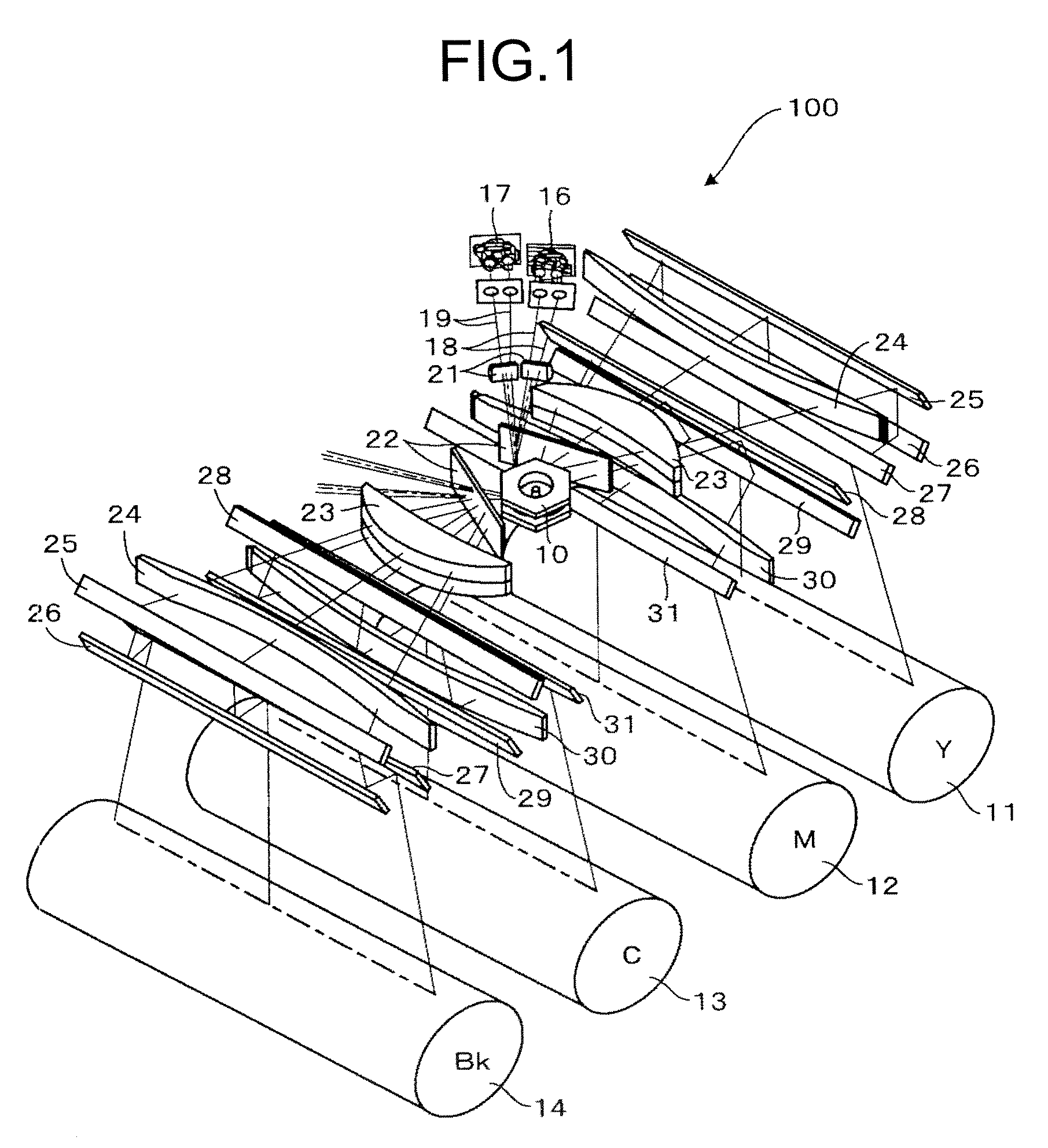
[0024]FIG. 1 is a perspective view of an optical scanning device 100 according to a first embodiment of the present invention. The optical scanning device 100 has a configuration of a facing scanning system in which electrostatic latent images are respectively formed on four photosensitive drums (image carriers) using one polygon scanner (deflector) 10.

[0025] Four photosensitive drums 11, 12, 13, and 14 are arranged along a moving direction of an intermediate transfer belt 15 (see FIG. 4) at equal intervals, and they form a color image by sequentially transferring toner images with different colors to superimpose the images.

[0026] According to the first embodiment, a pair of semiconductor lasers described later are arranged to each of the photosensitive drums 11, 12, 13, and 14 so that two lines are simultaneously scanned by performing scanning while...


PUM


Abstract

An optical scanning device includes a light source, a deflector that deflects a light beam from the light source, a first optical system that guides the light beam to the deflector, a second optical system that guides the light beam from the deflector to a surface to be scanned, and a housing that holds the light source and the deflector. At least one optical element included in the first optical system or the second optical system is attached to the housing via an intermediate member. The optical element is adjustable with respect to the intermediate member. The number of directions in which the optical element can be adjusted is two or more.

Description

CROSS-REFERENCE TO RELATED APPLICATIONS [0001] The present document incorporates by reference the entire contents of Japanese priority document, 2005-179828 filed in Japan on Jun. 20, 2005. BACKGROUND OF THE INVENTION [0002] 1. Field of the Invention [0003] The present invention relates to an optical scanning device that forms a latent image on an image carrier and an image forming apparatus employing the optical scanning device. [0004] 2. Description of the Related Art [0005] Recently, along with an improvement in the quality and density growth in image forming apparatuses such as a laser printer, there are increasing demands for reduction in diameter of a beam spot, reduction in positional deviation of the beam spot, and cost reduction in optical scanning devices. [0006] To satisfy these demands, although there is an approach of working respective optical parts with high precision and arranging the optical parts in a housing with high precision, the cost for manufacturing the opti...

Claims


Application Information

Patent Timeline
Patent Type & Authority Applications(United States)
IPC IPC(8): B41J15/14
CPCG02B26/123B41J2/473
Inventor HAYASHI, YOSHINORIOHSUGI, TOMOYASAISHO, KENICHIROHNAOE, YASUHIROOKUWAKI, HIROYUKIHIRAI, RYOUJI
Owner RICOH KK
Why Eureka
Try Eureka