Distance measuring device and method thereof

a technology of distance measurement and measuring device, which is applied in the direction of distance measurement, instruments, surveying and navigation, etc., can solve the problems of degradation in and achieve the effect of reducing the time required for a distance measurement without degrading the accuracy of measured valu

Active Publication Date: 2006-12-21
KK TOPCON
View PDF6 Cites 18 Cited by
  • Summary
  • Abstract
  • Description
  • Claims
  • Application Information

AI Technical Summary

Benefits of technology

[0016] The present invention has been made in view of the problem described above, and an object thereof is, in a distance measuring device by a phase difference method, to reduce the time required for a distance measurement without degrading accuracy of the measured value.

Problems solved by technology

Therefore, in order to reduce the time required for a measurement of the distance measuring device, if a reduction in the number of cycles of the intermediate frequency signal IF to be sampled is attempted, in, particularly, the case of a long-distance measurement, deficiency in the receiving light amount of the distance measuring light L frequently occurs owing to shimmering of air from heat, therefore, a problem of degradation in accuracy of the measured value arises.

Method used


Image

  • Distance measuring device and method thereof
  • Distance measuring device and method thereof
  • Distance measuring device and method thereof

Examples


Embodiment Construction

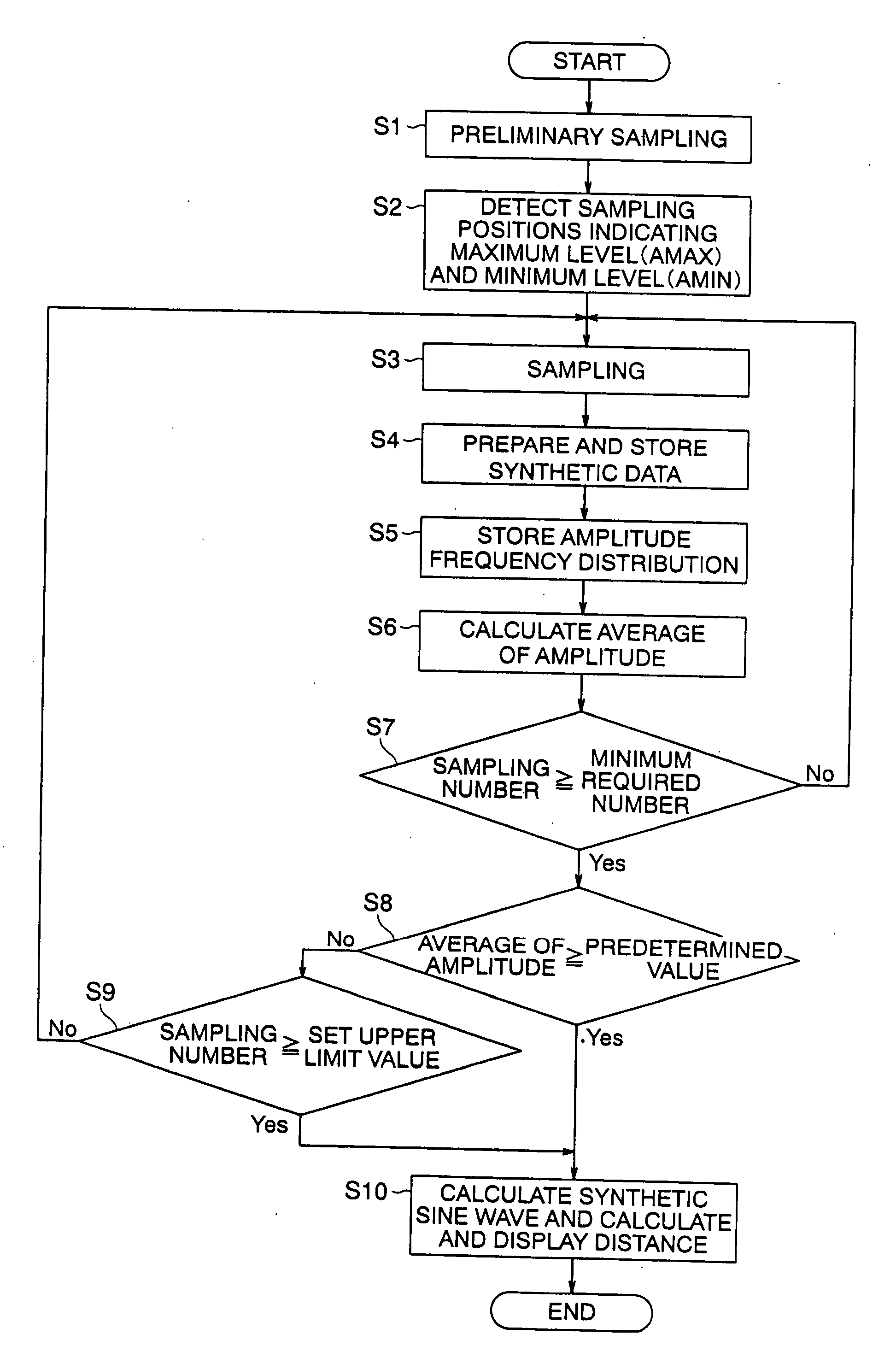
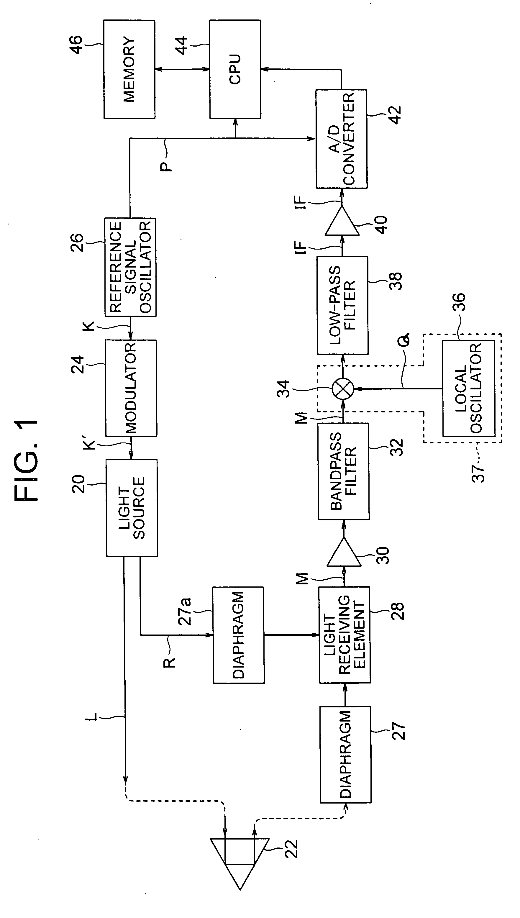
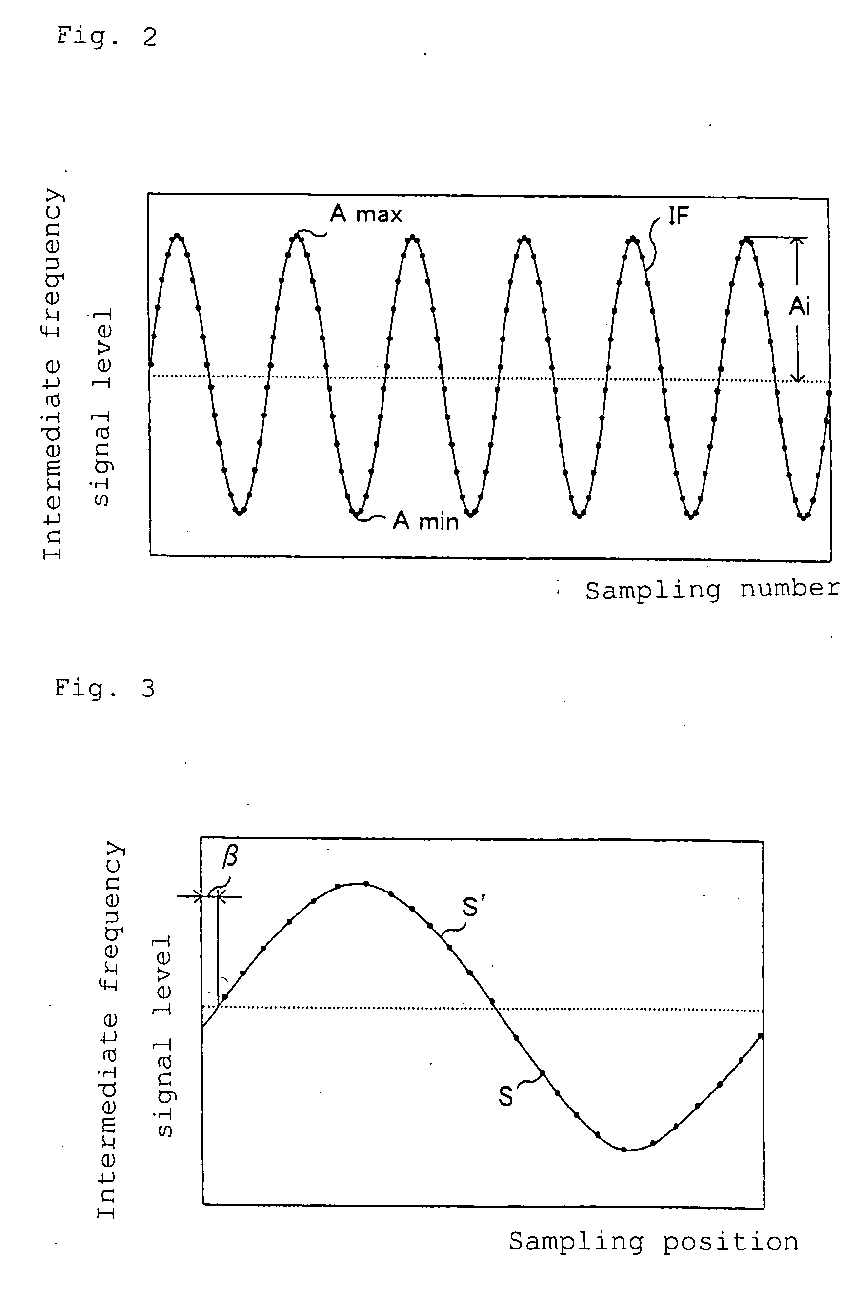
[0034] This distance measuring device also has a configuration shown by the same block diagram as that of the conventional distance measuring device shown in FIG. 1, and this samples, as shown in FIG. 2, an intermediate frequency signal IF for a large number of cycles, as shown in FIG. 3, adds sampling data of the intermediate frequency signal IF at the same phase position to determine synthetic data S, determines a synthetic sine wave S′ by calculation while applying the synthetic data S to a sine wave form, and calculates a distance based on an initial phase P of the synthetic sine wave S′. Therefore, description of the same parts of the distance measuring device as those of the conventional art will be omitted.

[0035] However, when determining sampling data, the CPU 44 of this distance measuring device does not always sample the intermediate frequency signal IF for more than a few thousands of a large number of cycles as in the conventional art, but ends sampling, if it judges th...


PUM


Abstract

A distance measuring device is provided that reduces the time required for a distance measurement without degrading accuracy of the measured value. The distance measuring device includes a reference signal oscillator (26) that generates a reference signal (K), a light source (20) that emits a distance measuring light (L) modulated based on the reference signal, a light receiving element (28) that receives the distance measuring light reflected from a target (22) and converts the distance measuring light to a distance measuring signal (M), a frequency converter (37) that converts the distance measuring signal to an intermediate frequency signal, an A/D converter (42) that samples the intermediate frequency signal in synchronization with the reference signal, a memory (46) that stores data of the sampled intermediate frequency signal, and a CPU (44) that calculates a distance based on the intermediate frequency signal data, the CPU calculates amplitude of each frequency of the intermediate frequency signal based on the intermediate frequency signal data, determines an average of the amplitude, and ends sampling to calculate a distance when the number of pieces of the intermediate frequency signal data is equal to or more than a minimum required number and the average has become equal to or more than a predetermined value.

Description

BACKGROUND OF THE INVENTION [0001] The present invention relates to a distance measuring device by a phase difference method that emits a distance measuring light toward a target and receives a reflected light from the target. [0002] A conventional distance measuring device will be described with reference to FIG. 1 to FIG. 3. [0003] As shown in the block diagram of FIG. 1, in this distance measuring device, a distance measuring light L transmitted from a light source 20 such as a laser diode is emitted toward a target (such as a prism) 22 placed on a survey point via an unillustrated light transmitting optical system. Since the light source 20 is connected to a modulator 24, the distance measuring light L is transmitted by a signal K′ modulated based on a reference signal K generated by a reference signal oscillator 26. [0004] The distance measuring light L reflected on the target 22 is led to a light receiving element 28 such as a photo diode via an unillustrated light receiving o...

Claims


Application Information

Patent Timeline
Patent Type & Authority Applications(United States)
IPC IPC(8): G01C3/08
CPCG01S17/36
Inventor AOKI, AKIHIRONAKAMURA, YUTAKASASAKI, KOJIUCHIMURA, TOSHIHIROOSADA, FUTOSHIKIKAWA, HAYAMI
Owner KK TOPCON
Why Eureka
Try Eureka