
Phase-sensitive amplification in a fiber

a phase-sensitive amplification and fiber technology, applied in the direction of laser optical devices, laser details, electrical apparatus, etc., can solve the problem that the psas suitable for use in fiber-based optical communication systems is not yet sufficiently developed

Active Publication Date: 2006-12-21
RPX CORP +1
View PDF6 Cites 38 Cited by
  • Summary
  • Abstract
  • Description
  • Claims
  • Application Information

AI Technical Summary

Benefits of technology

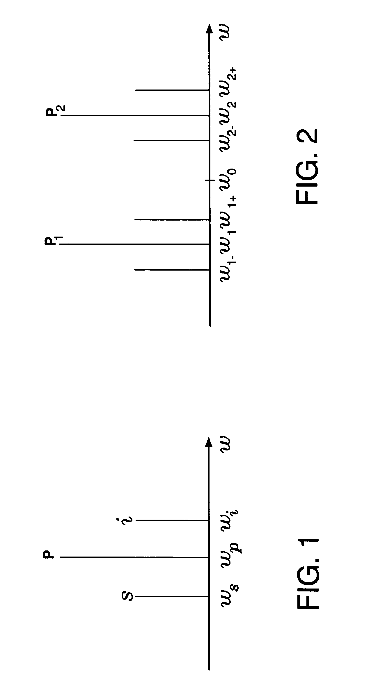
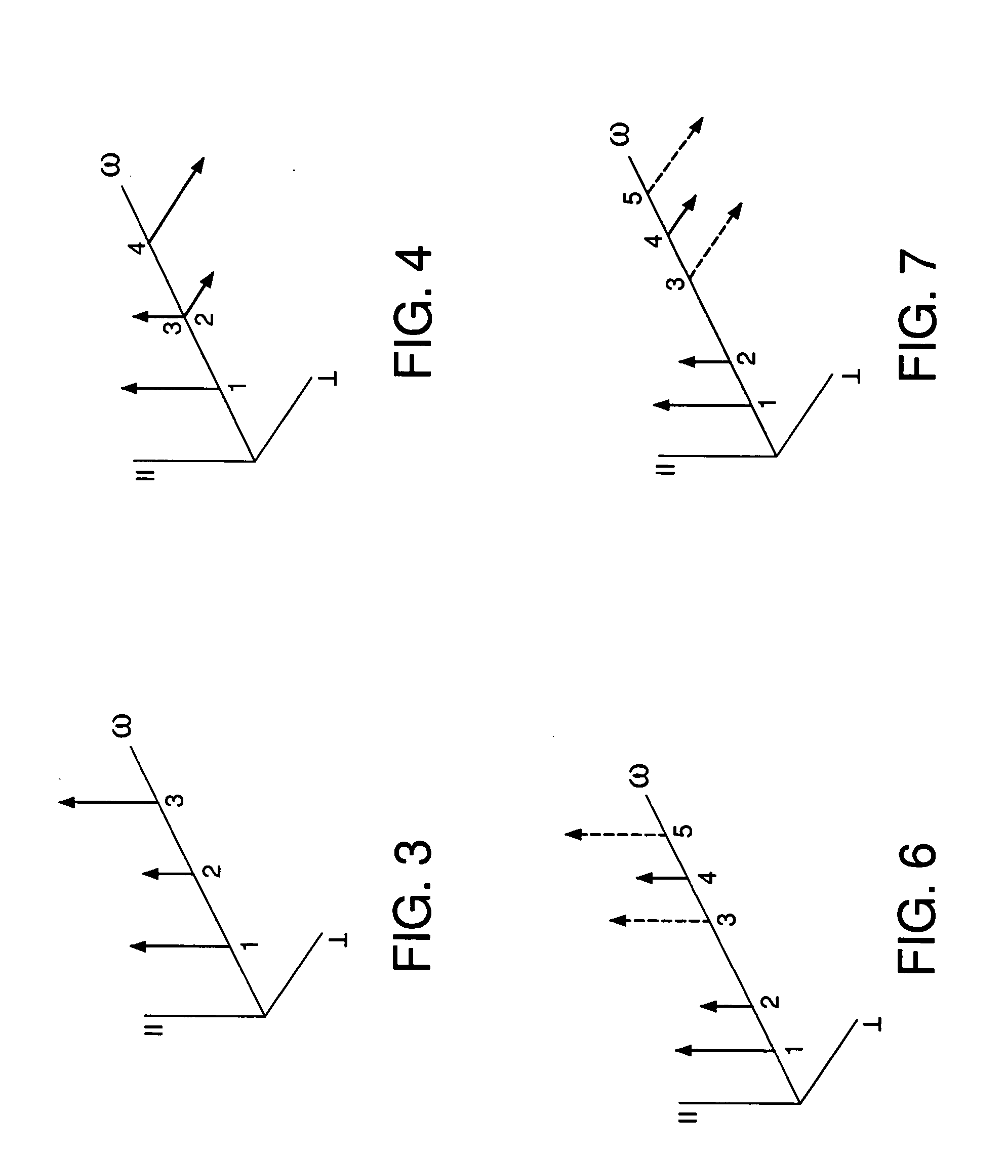
[0005] Problems in the prior art are addressed, in accordance with the principles of the present invention, by a method of and device for generating an amplified optical signal directly in an optical fiber by way of phase-sensitive amplification based on one or more four-wave mixing (FWM) processes. In one embodiment, an input signal and two pump waves are applied to a highly nonlinear fiber (HNLF). The input signal is amplified in the HNLF due to energy transfer from the pump waves to the input signal via a degenerate phase-conjugation (PC) process. The amplified signal is then separated from the pump waves by an optical filter placed at the end of the HNLF.

Problems solved by technology

However, PSAs suitable for use in fiber-based optical communication systems are not yet sufficiently developed.

Method used


Image

  • Phase-sensitive amplification in a fiber
  • Phase-sensitive amplification in a fiber
  • Phase-sensitive amplification in a fiber

Examples


Embodiment Construction

[0016] Reference herein to “one embodiment” or “an embodiment” means that a particular feature, structure, or characteristic described in connection with the embodiment can be included in at least one embodiment of the invention. The appearances of the phrase “in one embodiment” in various places in the specification are not necessarily all referring to the same embodiment, nor are separate or alternative embodiments mutually exclusive of other embodiments.

Optical Parametric Amplification

[0017] As known in the art, optical parametric amplification (OPA) is a process that produces a tunable coherent optical signal via nonlinear optical processes, in which, typically, one or two pump-wave photons are converted into two new photons with conservation of photon energy and momentum. The waves corresponding to the two new photons are usually referred to as a signal and an idler. An excellent review of the fundamentals of OPA can be found in a book by G. P. Agrawal, “Nonlinear Fiber Opti...


PUM


Abstract

A method of and device for generating an amplified optical signal directly in an optical fiber by way of phase-sensitive amplification based on one or more four-wave mixing (FWM) processes. In one embodiment, an input signal and two pump waves are applied to a highly nonlinear fiber (HNLF). The input signal is amplified in the HNLF due to energy transfer from the pump waves to the input signal via a degenerate phase-conjugation (PC) process. In another embodiment, an input signal and first and second pump waves are applied to a first HNLF to generate, via a Bragg scattering (BS) process, an idler signal corresponding to the input signal. The second pump wave is then filtered out and the first pump wave, a third pump wave, and the input and idler signals are applied to a second HNLF, where they interact via a non-degenerate PC process to produce an amplified output signal.

Description

BACKGROUND OF THE INVENTION [0001] 1. Field of the Invention [0002] The present invention relates to optical communication equipment and, more specifically, to optical amplifiers. [0003] 2. Description of the Related Art [0004] Optical communication systems employ optical amplifiers, e.g., to compensate for signal attenuation in optical fibers. One type of amplifier that may be used in a fiber-based optical communication system is an optical fiber amplifier (OFA). Many current optical communication systems employ erbium-doped and / or Raman fiber amplifiers. These amplifiers are examples of phase-insensitive amplifiers (PIAs). More specifically, a PIA produces signal gain that is independent of the signal phase. In contrast, a phase-sensitive amplifier (PSA) produces signal gain that does depend on the signal phase. Potential advantages of using PSAs instead of or in addition to PIAs in optical communication systems include, but are not limited to, noise reduction, the reduction of no...

Claims


Application Information

Patent Timeline
Patent Type & Authority Applications(United States)
IPC IPC(8): H01S3/00
CPCH01S3/005H01S3/06758H01S3/06725H01S3/0078
Inventor MCKINSTRIE, COLIN J.
Owner RPX CORP
Learn More