Ion diffusing

a technology of ion diffusing and ion generating efficiency, which is applied in the direction of domestic cooling apparatus, corona discharge, instruments, etc., can solve the problems of insufficientness, achieve the effect of enhancing ion generating efficiency and ion transfer efficiency, reducing disturbance or drift, and reducing the difficulty of ion generating and transferring

Active Publication Date: 2006-12-21
SHARP KK
View PDF9 Cites 31 Cited by
  • Summary
  • Abstract
  • Description
  • Claims
  • Application Information

AI Technical Summary

Benefits of technology

[0025] According to the present invention, it is possible to suppress the disturbance or drift generated in the vicinity of the ion generating apparatus and to enhance the ion generating efficiency and ion transfer efficiency by providing a rectifier or a narrow portion, and it is possible to realize an ion diffusing apparatus having higher ability.
[0026] According to the present invention, the w

Problems solved by technology

In FIG. 37, although there exist ions having high concentration around the outer-s

Method used


Image

  • Ion diffusing
  • Ion diffusing
  • Ion diffusing

Examples


first embodiment

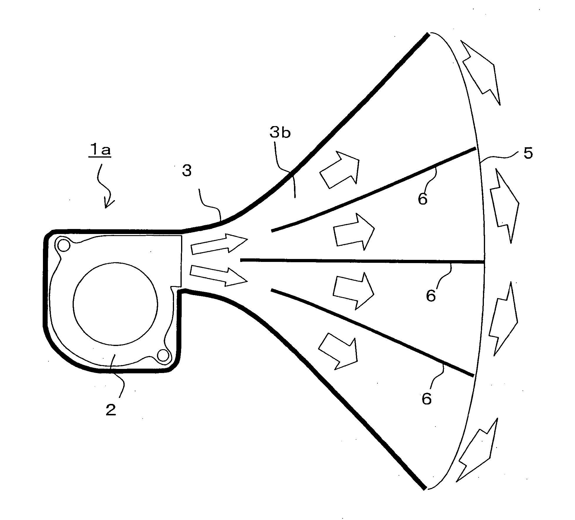
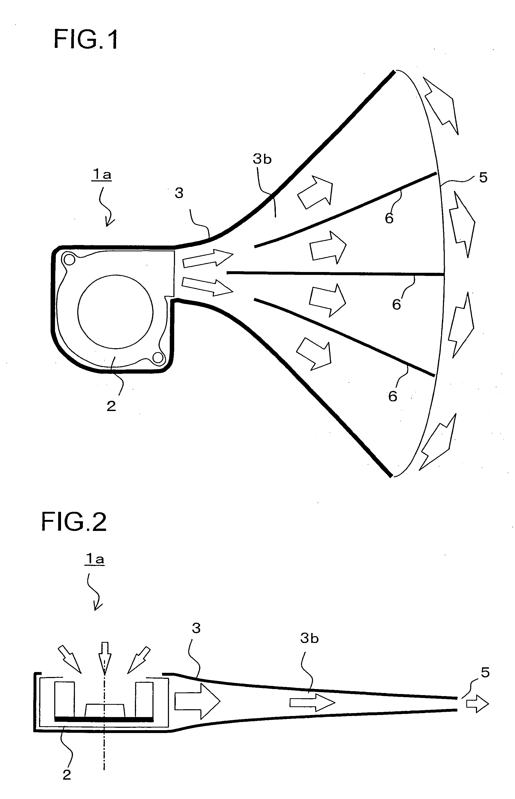
[0101] A first embodiment will be explained.FIG. 1 is a schematic sectional plan view showing a fluid generating apparatus of the first embodiment, and FIG. 2 is a schematic sectional side view showing the fluid generating apparatus of the embodiment. A fluid generating apparatus 1a of this embodiment includes a fluid sending apparatus 2 which sends out fluid such as gas and liquid, a fluid flowing passage 3 which transmits the fluid sent out from the fluid sending apparatus 2, a blowout opening 5 formed in an end of the fluid flowing passage 3 for sending out the fluid as a jet stream, and a control section (not shown). The fluid is transmitted by the operation of the fluid sending apparatus 2, flows through the fluid flowing passage 3 and is emitted outside from the blowout opening 5 as the jet stream. In the drawings, arrows show a flow of the fluid.

[0102] In the fluid flowing passage 3, upstream portions of the blowout opening 5 comprise enlarged pipe portions 3b. The enlarged ...

second embodiment

[0116] A second embodiment will be explained next. FIG. 7 is a schematic sectional plan view showing a fluid generating apparatus according to the second embodiment, and FIG. 8 is a schematic sectional side view showing the fluid generating apparatus according to the second embodiment.

[0117] In the second embodiment, the guiding plates 6 of the first embodiment are omitted, and the fluid flowing passage 3 is divided by a plurality of enlarged pipe portions 3b from the downstream portion immediately after the fluid sending apparatus 2. In this embodiment, the fluid flowing passage 3 is divided into two enlarged pipe portions 3b in the lateral direction and two enlarged pipe portions 3b in the vertical direction, i.e., the fluid flowing passage 3 is divided into total four enlarged pipe portions 3b and thus, four blowout openings 5 are provided. The divided fluid flowing passage 3 and their enlarged pipe portions 3b are designed such that the aspect ratios are increased as they appro...

third embodiment

[0121] A third embodiment will be explained next. FIG. 10 is a perspective view showing a fluid generating apparatus of the third embodiment.

[0122] Like the other embodiment in the second embodiment, the shape of the blowout opening 5 of a fluid generating apparatus 1d of the third embodiment has the relation of height>width. The fluid flowing passage 3 is divided into seven enlarged pipe portions 3b in the lateral direction and two enlarged pipe portions 3b in the vertical direction, i.e., the fluid flowing passage 3 is divided into total fourteen enlarged pipe portions 3b and thus, fourteen blowout openings 5 are provided. The divided fluid flowing passage 3 and their enlarged pipe portions 3b are designed such that the aspect ratios are increased as they approach the blowout opening 5, and the aspect ratio thereof at the position of the blowout opening 5 (in this case, height of the blowout opening / width of the blowout opening) is set to about 8. Other structures are the same as...


PUM


Abstract

It is an object of the invention to provide an ion diffusing apparatus having higher ability by suppressing the disturbance or turbulent flow generated in the vicinity of an ion generating apparatus and by enhancing the ion generating efficiency and the ion transfer efficiency. To achieve this object, the ion diffusing apparatus includes an ion generating apparatus which generates ions from an electrical discharging surface, a wind-blowing path which transmits the ions generated from the ion generating apparatus, and a blowout opening which is formed in an end of the wind-blowing path and which discharges the ions, and the wind-blowing path upstream from the ion generating apparatus is provided with a rectifier which rectifies flow of ions.

Description

TECHNICAL FIELD [0001] The present invention relates to an ion diffusing apparatus which discharges ions in a wide range. BACKGROUND ART [0002] One example of conventional ion diffusing apparatuses is described in a later-described comparative example 2 (see FIG. 36). A refrigerator having this ion diffusing apparatus 110a (see FIG. 35) is described in Patent Publications 1 and 2. This refrigerator 200 emits ions outside the refrigerator to sterilize the outer periphery of the refrigerator. By sterilizing suspended bacteria outside the refrigerator, sanitary living space is provided, and it is possible to prevent suspended bacteria from entering the refrigerator from outside when its door is opened / closed, and to provide sanitary inside environment of the refrigerator. [0003]FIG. 37 shows ion concentrations of various portions in a room at 15° C. in temperature when cluster ions are discharged into the room from an outer-side ion blowout opening 22 of a refrigerator 200 having a con...

Claims


Application Information

Patent Timeline
IPC IPC(8): A61L9/22F25D17/04
CPCF25D17/042F25D23/003F25D23/12A61L9/22B01J19/08F25D17/04F25D23/00
Inventor OHTSUKA, MASAKIINOUE, YOSHIKAZUYOSHIKAWA, TAKASHI
Owner SHARP KK
Why Eureka
Try Eureka