
Negative ion generator using carbon fiber

a carbon fiber and negative ion technology, applied in the field of negative ion generators, can solve the problems of low difficult manufacture and management, increased cost, etc., and achieve the effect of improving negative ion generation efficiency and being easy to manufactur

Inactive Publication Date: 2005-12-08
LG ELECTRONICS INC
View PDF15 Cites 10 Cited by
  • Summary
  • Abstract
  • Description
  • Claims
  • Application Information

AI Technical Summary

Benefits of technology

[0008] Therefore, an object of the present invention is to provide a negative ion generator using an inexpensive carbon fiber, improving negative ion generation efficiency, and easily manufactured while providing both antimicrobial and sterilizing functions.

Problems solved by technology

In contrast, a state that a molecule has positive charge is called a positive ion, which is known to be harmful to a human body because it causes vomiting or dizziness.
However, the ion generator in accordance with the conventional art has problems in that negative ion generation efficiency is low.
For this reason, the configuration of the system becomes complicated, which results in the difficult manufacture and management and a cost increase.

Method used


Image

  • Negative ion generator using carbon fiber
  • Negative ion generator using carbon fiber
  • Negative ion generator using carbon fiber

Examples


first embodiment

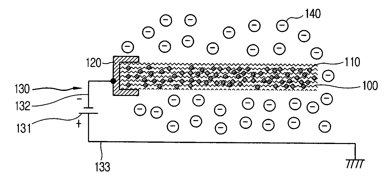
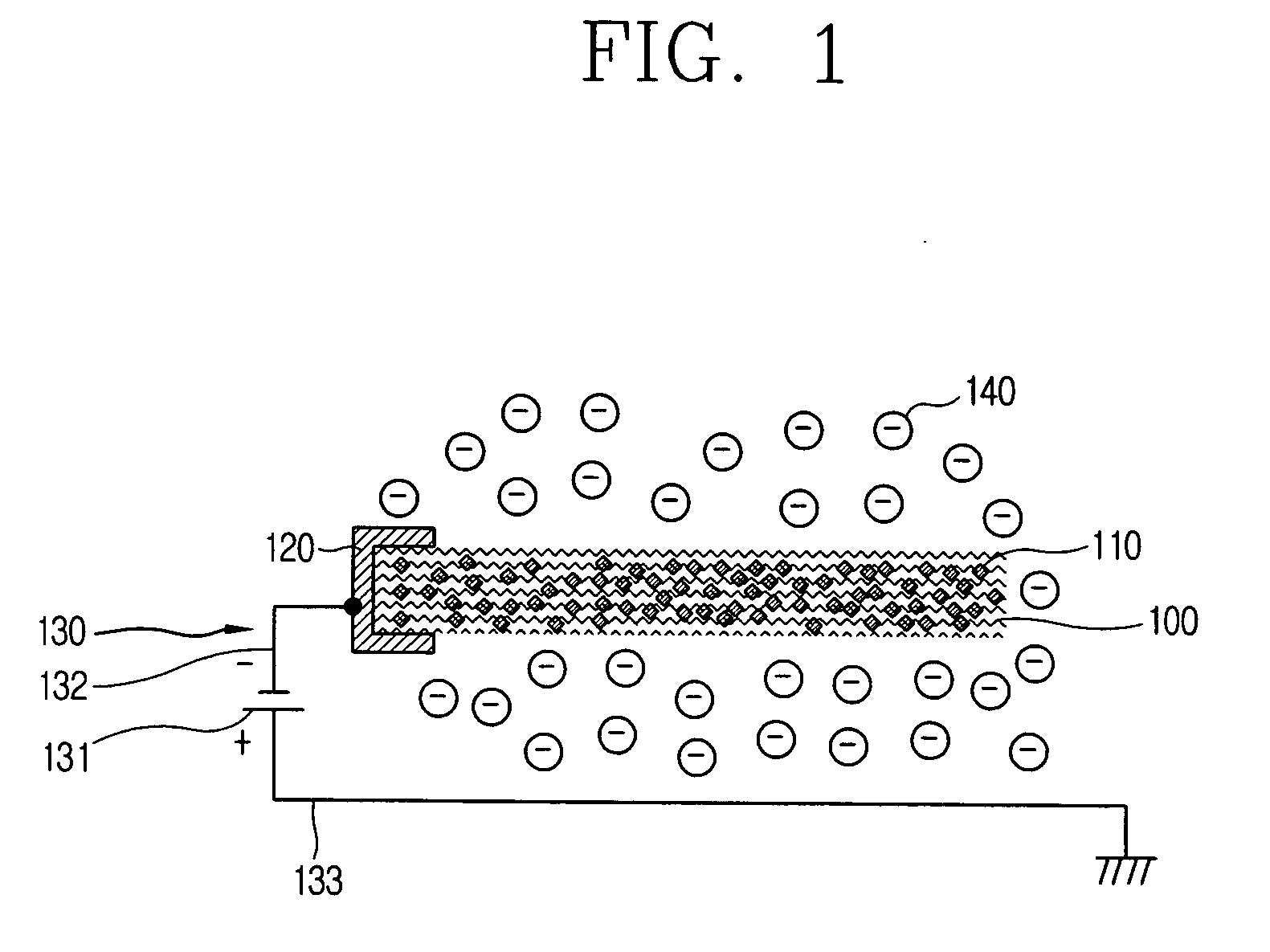
[0023]FIG. 1 is a sectional view showing a negative ion generator using a carbon fiber in accordance with the present invention.

[0024] As shown, the negative ion generator in accordance with the present invention includes: an activated carbon fiber 100 in which metallic particles 110 are distributed; an electrode 120 connected to the activated carbon fiber 100 and applying a voltage thereto; and a power unit 130 for supplying power to the electrode 120.

[0025] Ag, Pt, Au, Cu, Al, Cr, W, Mo or the like may be used as the metallic particle 110, and the metallic particles 110 are evenly distributed in the activated carbon fiber 100. The activated carbon fiber 100 will be described afterwards.

[0026] In the present embodiment, Ag is used as the metallic particle 110. It is a known fact that said Ag can kill germs. Accordingly, said Ag is used to add an antimicrobial function to the negative ion generator.

[0027] Preferably, the electrode is attached to a side of the activated carbon fib...

second embodiment

[0040]FIG. 5 is a sectional view showing a negative ion generator using a carbon fiber in accordance with the present invention.

[0041] In the second embodiment of the present invention, a structure of an electrode is different from that of the first embodiment. As shown in FIG. 5, an entire surface of one side of the electrode 220 is in contact with the activated carbon fiber 100. Also, an entire surface of the other electrode 220 is in contact with a non-conductive substrate 230.

[0042] In the second embodiment, a voltage applied from a power unit 130 is evenly applied to the activated carbon fiber 100, so that negative ions 140 are uniformly generated. Namely, the negative ion can be uniformly generated regardless of time. However, such uniform negative ion generation interrupts communication between the air and the activated carbon fiber 100. For this reason, the negative ion generator in accordance with the second embodiment is not appropriate to absorb foreign substances or rem...


PUM

PropertyMeasurementUnit
distanceaaaaaaaaaa
distanceaaaaaaaaaa
voltageaaaaaaaaaa

Abstract

A negative ion generator using a carbon fiber can facilitate its manufacturing process, improve negative ion generation efficiency and implement improved antimicrobial and sterilizing functions by distributing metallic particles in an activated carbon fiber and then applying a voltage thereto. To this end, the negative ion generator comprises: a carbon fiber in which metallic particles are distributed; an electrode connected to the carbon fiber and applying a voltage thereto; and a power unit for supplying power to the electrode.

Description

BACKGROUND OF THE INVENTION [0001] 1. Field of the Invention [0002] The present invention relates to a negative ion generator, and particularly, to a negative ion generator using a carbon fiber capable of facilitating its manufacturing process, improving negative ion generation efficiency and implementing improved antimicrobial and sterilizing functions by distributing metallic particles in an activated carbon fiber and then applying a voltage thereto. [0003] 2. Description of the Background Art [0004] As problems caused by air pollution such as smoke, sand dust phenomena or the like have got worse recently, people are being increasingly interested in clean and fresh air. Since the number of people suffering from various kinds of respiratory diseases or having allergies to polluted air is increasing, several attempts to purify the polluted air by generating negative ions are being made in different ways over various fields. [0005] The negative ion means a state that a molecule such ...

Claims


Application Information

Patent Timeline
Patent Type & Authority Applications(United States)
IPC IPC(8): A61L9/22A61L9/01A61L9/16H01T23/00
CPCH01T23/00A61L9/22A61L2209/14B82Y99/00
Inventor KIM, HWA-NYEONHONG, HYUNG-KIJUNG, MIN-JAEJI, KWANG-SUNLEE, DON-HEEPARK, SANG-HOKIM, YOUNG-WOOKANG, BYEONG-GYU
Owner LG ELECTRONICS INC
Learn More