Ionization method and apparatus including applying converged shock waves to a spray

a shock wave and converged technology, applied in the direction of particle separator tube details, instruments, separation processes, etc., can solve the problems of waste of sample components in droplets that do not enter the heated capillary tube, inability to perform drying processes, and insufficient vaporization of solvent in a short time, so as to improve detection accuracy and detection accuracy, improve detection sensitivity and efficiency, and increase the amount of ions

Inactive Publication Date: 2015-08-11
SHIMADZU CORP
View PDF34 Cites 0 Cited by
  • Summary
  • Abstract
  • Description
  • Claims
  • Application Information

AI Technical Summary

Benefits of technology

[0024]According to an ionization method relating to a first aspect of the present invention and an ionization apparatus relating to a second aspect of the present invention, ion generation efficiency can be improved and a higher amount of ions can be supplied to a mass spectrometry, compared to conventional methods and apparatuses. Therefore, detection sensitivity and detection accuracy are improved, resulting in the contribution to improvements in the qualitative and quantitative accuracy.
[0025]Also, according to the ionization method relating to the third aspect of the present invention and the ionization apparatus relating to the fourth aspect of the present invention, a component in a caked-state sample can be ionized by a method completely different from conventional methods. Since energy of the ionization directly acts on the sample component, the ionization can be performed at high efficiency without using auxiliary materials, such as a matrix used in MALDI.

Problems solved by technology

However, in such a conventionally adopted heating method, any drying processes cannot be performed but only a drying process by the ambient temperature at several hundred degrees Celsius at the highest.
This is not necessarily enough to vaporize the solvent in a short time.
However, it is unavoidable that sample components in the droplets that do not enter the heated capillary tube will be wasted.
Particularly, in the ESI, since the size of each of the droplets sprayed from the nozzle 1 is relatively large, it is not easy for the solvent in each of the droplets to vaporize, causing the ratio of the wasted sample components to be large.
However, there is a problem that it is difficult to enhance ionization efficiency in the case of the LDI without using a matrix.
In the case of the MALDI also, there are some problems, such that a matrix having an adequate laser beam absorbing quality must be chosen, and a large difference in the sensitivity may arise depending on the mixing state of the sample crystal and the matrix.

Method used


Image

  • Ionization method and apparatus including applying converged shock waves to a spray
  • Ionization method and apparatus including applying converged shock waves to a spray
  • Ionization method and apparatus including applying converged shock waves to a spray

Examples


first embodiment

[0047][First Embodiment]

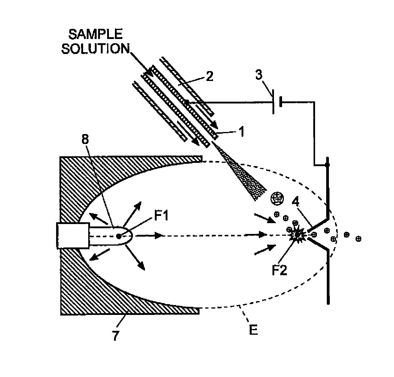
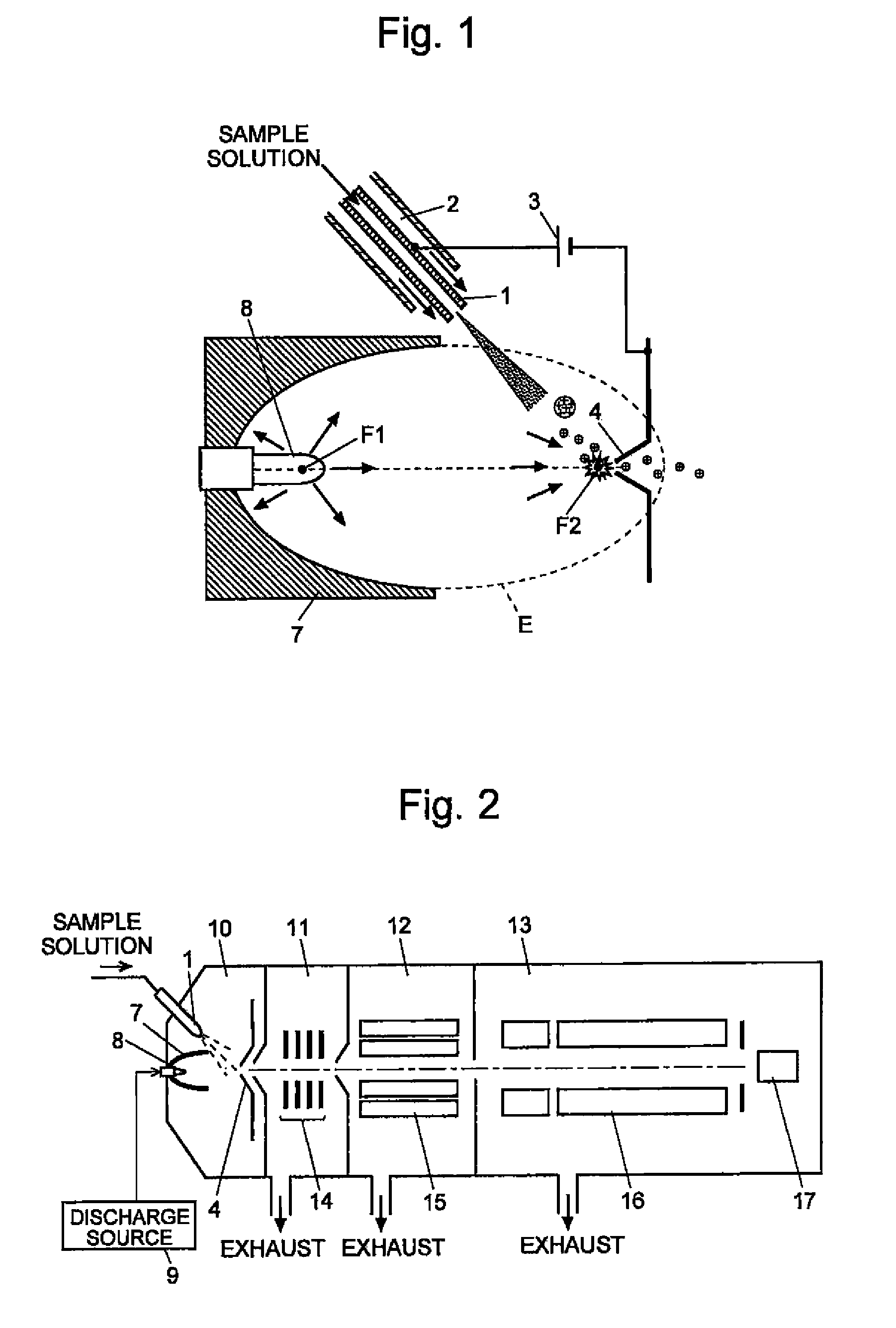
[0048]An ionization apparatus according to an embodiment (a first embodiment) of the present invention is described, referring to the attached drawings. FIG. 1 is a schematic configuration diagram of the ionization apparatus according to the present embodiment, and FiG. 2 is an overall configuration diagram showing an example of amass spectrometer using The ionization apparatus.

[0049]As shown in FIG. 2, in the mass spectrometer, two intermediate vacuum chambers 11, 12 are provided between an ionization chamber 10 maintained at an atmosphere at approximately atmospheric pressure and an analysis chamber 13 maintained at a high vacuum atmosphere. Thus, the mass spectrometer adopts a configuration of a multistage differential exhaust system enhancing the degree of vacuum gradually from the ionization chamber 10 toward the analysis chamber 13. In the ionization chamber 10, the sample components in a sample solution are ionized by an ionization apparatus which will...

second embodiment

[0057][Second Embodiment]

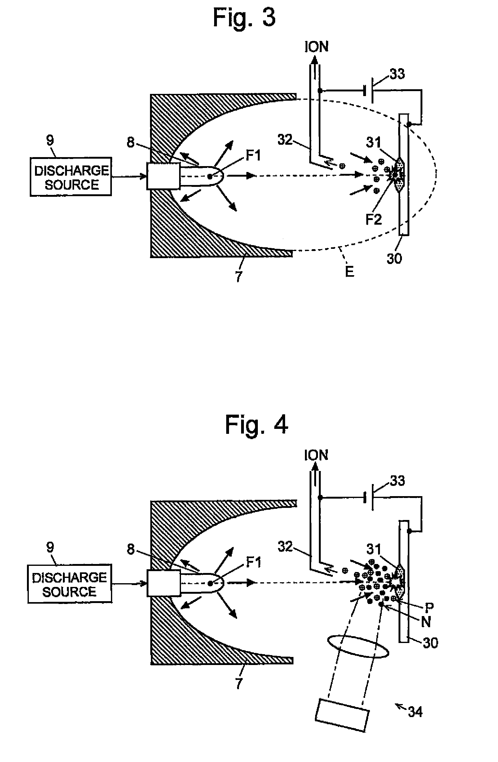
[0058]Next, an ionization apparatus according to another embodiment (second embodiment) of the present invention is described, referring to the attached drawings. FIG. 3 is a schematic diagram showing the ionization apparatus according to the second embodiment.

[0059]Although the same components as in the first embodiment are used in the second embodiment with respect to the shock wave generating means, specifically, the reflector 7, the discharge electrode 8 and the discharge source 9, the second focal point F2 of the spheroid E is to be positioned on a surface of a sample 31 held on a sample stage 30 in the second embodiment. The sample 31 is a solid-state sample or a caked-state sample prepared by drying a sample solution. A capillary tube 32 for collecting ions and transmitting them to the later stage is arranged as an ion-introducing device between the sample stage 30 and the discharge electrode 8.

[0060]When a pulsed high voltage having a predetermined f...


PUM

PropertyMeasurementUnit
temperatureaaaaaaaaaa
pressureaaaaaaaaaa
temperatureaaaaaaaaaa

Abstract

A sample solution containing a sample component is sprayed onto an atmosphere at atmospheric approximately pressure while being applied with electric charge from the tip of a nozzle (1). A sample molecule is released as an ion in a process where charged minute liquid droplets collide with an atmospheric gas and are broken apart, and a solvent is vaporized from the respective liquid droplets. A reflectron (7) in the shape of a half-cut spheroid is arranged in such a manner that a second focal point (F2) is positioned in front of an ion-introducing portion (4) in the spray flow. A discharge electrode (8) is disposed in a position at a first focal point (F1) of the reflectron (7). When pulsed high voltage is applied to the discharge electrode (8), an electric discharge occurs, causing shock waves to be generated. The shock waves reflected on the reflectron (7) are converged on the second focal point (F2). Due to the converged shock waves, the vicinity of the second focal point (F2) rises to a high temperature, and a large pressure is also applied thereto. Therefore, vaporization of a solvent from the respective liquid droplets is further accelerated, allowing an ion to be easily generated. In addition, direct ionization can be expected. This makes it possible to improve ion generation efficiency.

Description

CROSS-REFERENCE TO THE RELATED APPLICATIONS[0001]This application is a national stage of international application No. PCT / JP2008 / 000610, filed on Mar. 17, 2008, the entire contents of which are incorporated herein by reference.TECHNICAL FIELD[0002]The present invention relates to an ionization method and an ionization apparatus in use for generating ions to be supplied to mass spectrometry.BACKGROUND ART[0003]When a sample solution containing a sample component separated by a column of a liquid chromatograph is analyzed by a mass spectrometer, an atmospheric pressure ionization method (API), such as an electrospray ionization method (ESI) and an atmospheric pressure chemical ionization method (APCI), is generally used (see Patent Document 1, for example). FIG. 6(A) is a diagram showing the principle configuration of the ESL and FIG. 6(B) is a diagram showing the principle configuration of the APCI.[0004]In the ESL the sample solution is introduced into a thin nozzle 1 having a tip ...

Claims


Application Information

Patent Timeline
Patent Type & Authority Patents(United States)
IPC IPC(8): H01J49/00G01N27/62H01J49/04H01J49/16
CPCG01N27/62H01J49/044H01J49/165
Inventor YAMAGUCHI, SHINICHI
Owner SHIMADZU CORP
Why Eureka
Try Eureka