Ionization Method and Ionization Apparatus
a technology of ionization apparatus and ionization method, which is applied in the direction of particle separator tube details, instruments, and dry process cannot be performed, and can solve the problems of sample components in droplets that do not enter the heated capillary tube, waste of sample components, and insufficient vaporization of solvent in a short time. , to achieve the effect of improving detection accuracy, reducing the amount of ions, and improving the efficiency of ion generation
- Summary
- Abstract
- Description
- Claims
- Application Information
AI Technical Summary
Benefits of technology
Problems solved by technology
Method used
Image
Examples
first embodiment
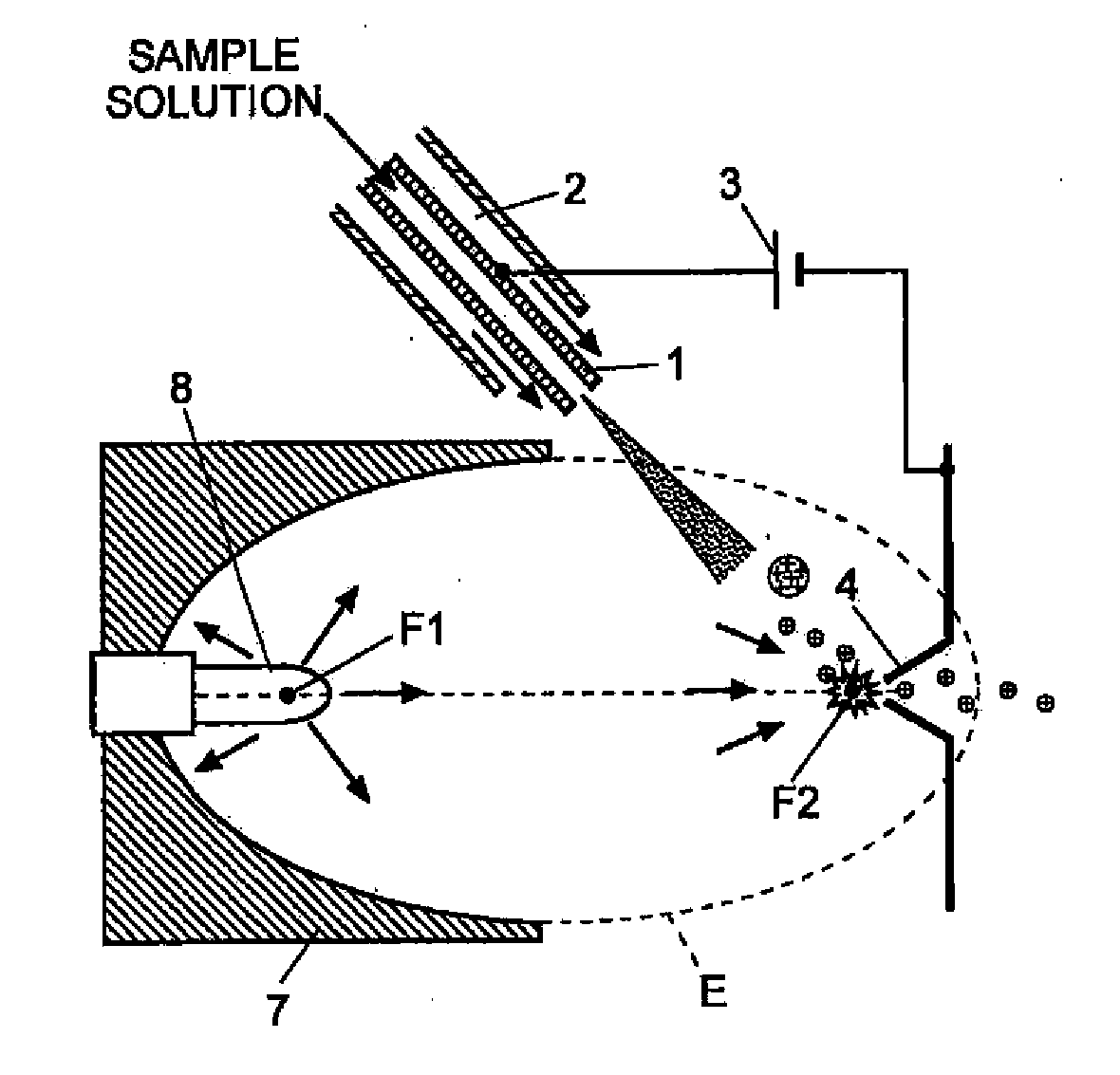
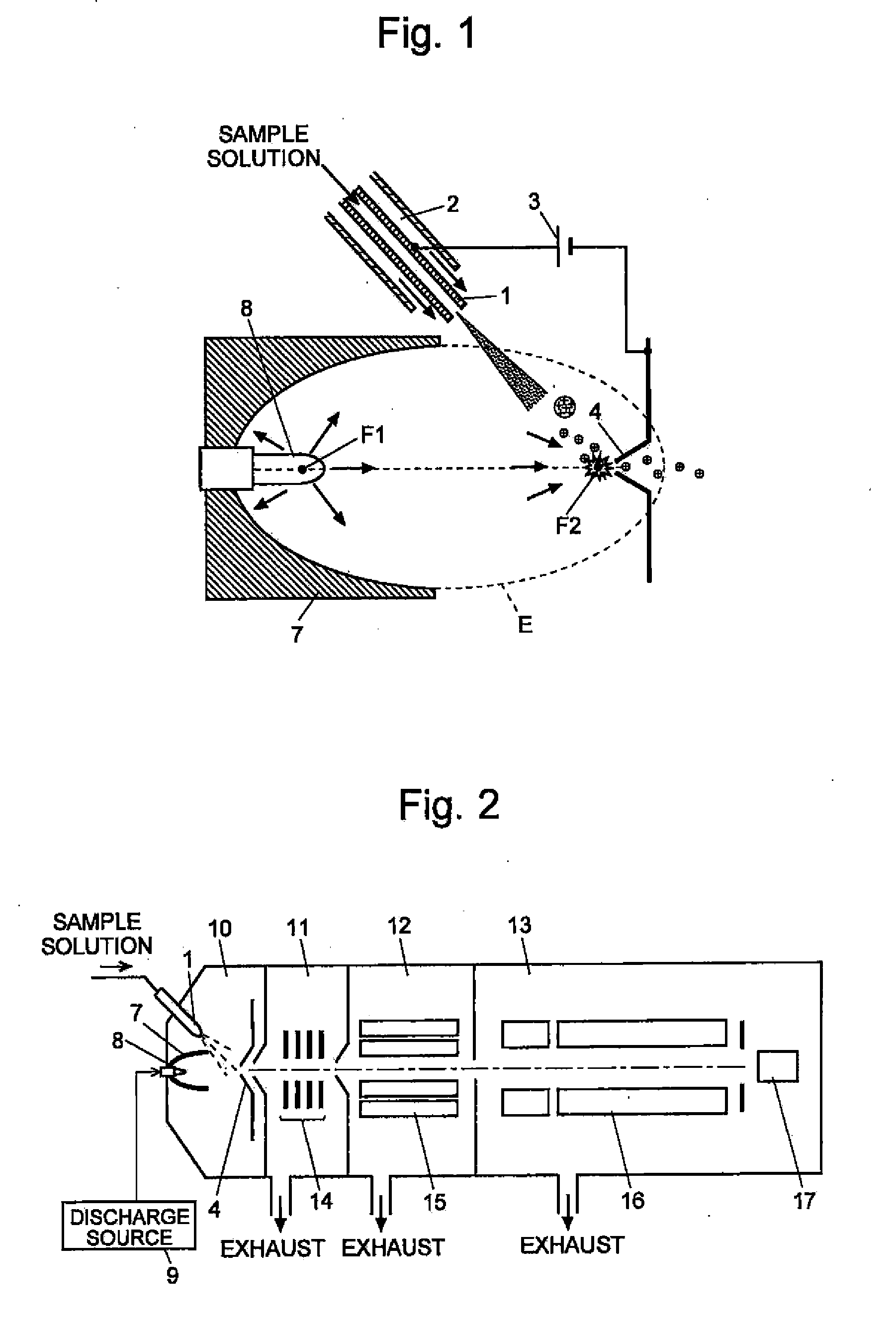
[0048]An ionization apparatus according to an embodiment (a first embodiment) of the present invention is described, referring to the attached drawings. FIG. 1 is a schematic configuration diagram of the ionization apparatus according to the present embodiment, and FIG. 2 is an overall configuration diagram showing an example of a mass spectrometer using the ionization apparatus.
[0049]As shown in FIG. 2, in the mass spectrometer, two intermediate vacuum chambers 12, 13 are provided between an ionization chamber 10 maintained at an atmosphere at approximately atmospheric pressure and an analysis chamber 13 maintained at a high vacuum atmosphere. Thus, the mass spectrometer adopts a configuration of a multistage differential exhaust system enhancing the degree of vacuum gradually from the ionization chamber 10 toward the analysis chamber 13. In the ionization chamber 10, the sample components in a sample solution are ionized by an ionization apparatus which will be described later. Th...
second embodiment
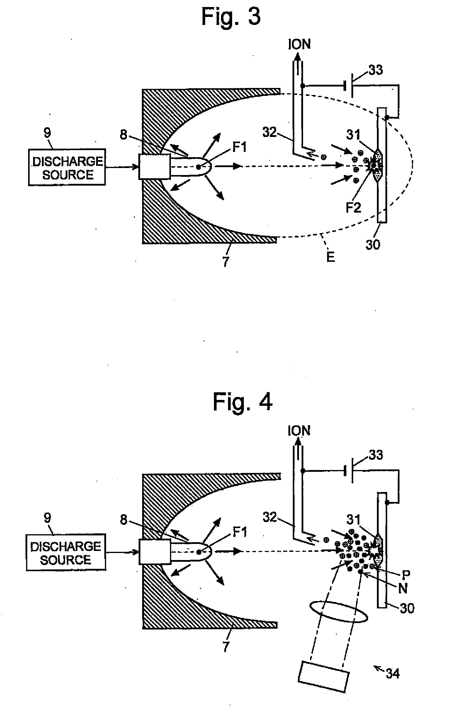
[0057]Next, an ionization apparatus according to another embodiment (second embodiment) of the present invention is described, referring to the attached drawings. FIG. 3 is a schematic diagram showing the ionization apparatus according to the second embodiment.
[0058]Although the same components as in the first embodiment are used in the second embodiment with respect to the shock wave generating means, specifically, the reflector 7, the discharge electrode 8 and the discharge source 9, the second focal point F2 of the spheroid E is to be positioned on a surface of a sample 31 held on a sample stage 30 in the second embodiment. The sample 31 is a solid-state sample or a caked-state sample prepared by drying a sample solution. A capillary tube 32 for collecting ions and transmitting them to the later stage is arranged as an ion-introducing device between the sample stage 30 and the discharge electrode 8.
[0059]When a pulsed high voltage having a predetermined form is applied from the d...
PUM
 Abstract
Description
Claims
Application Information
 - R&D
- Intellectual Property
- Life Sciences
- Materials
- Tech Scout
- Unparalleled Data Quality
- Higher Quality Content
- 60% Fewer Hallucinations
Browse by: Latest US Patents, China's latest patents, Technical Efficacy Thesaurus, Application Domain, Technology Topic, Popular Technical Reports.
© 2025 PatSnap. All rights reserved.Legal|Privacy policy|Modern Slavery Act Transparency Statement|Sitemap|About US| Contact US: help@patsnap.com


